Plunger pump

A technology of plunger pump and plunger machine, applied in the field of hydraulic plunger pump, can solve the problems of increasing manufacturing cost, energy loss, influence of service life of servo motor, etc., and achieve the effect of low cost and long life

Inactive Publication Date: 2010-03-31
HIGH TECH FLUID POWER CO LTD
View PDF0 Cites 17 Cited by
  • Summary
  • Abstract
  • Description
  • Claims
  • Application Information

AI Technical Summary

Problems solved by technology

Under normal working conditions, this power unit can match the flow required by the hydraulic system and control the working pressure of the system more precisely. unresolvable technical problems
If the system is in the working condition of high pressure and small flow for a long time, in order to ensure the stability of the pressure, high pressure overflow is used or the motor is kept in the state of high torque for a long time, which not only brings energy loss, but also affects the servo motor. In addition, when the system requires high-pressure and rapid pressure relief, this power unit can only be realized through delayed pressure relief and external control pressure relief, which not only reduces production efficiency, but also increases system manufacturing. cost

Method used


Image

  • Plunger pump
  • Plunger pump
  • Plunger pump

Examples


Embodiment Construction

[0013] The specific embodiments of the present invention will be further described in detail below in conjunction with the accompanying drawings.

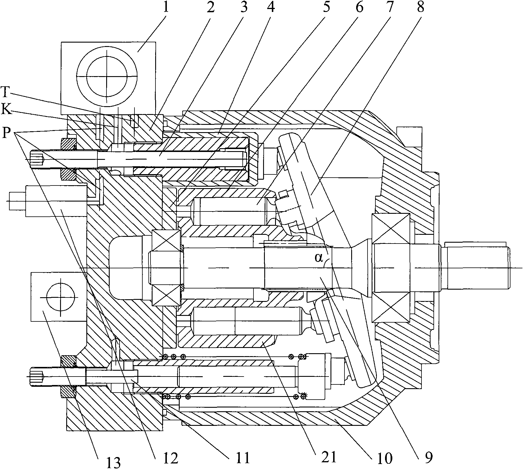
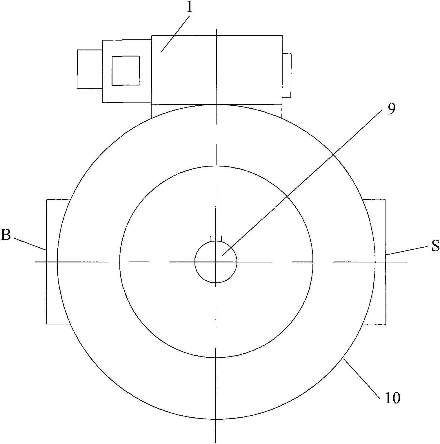
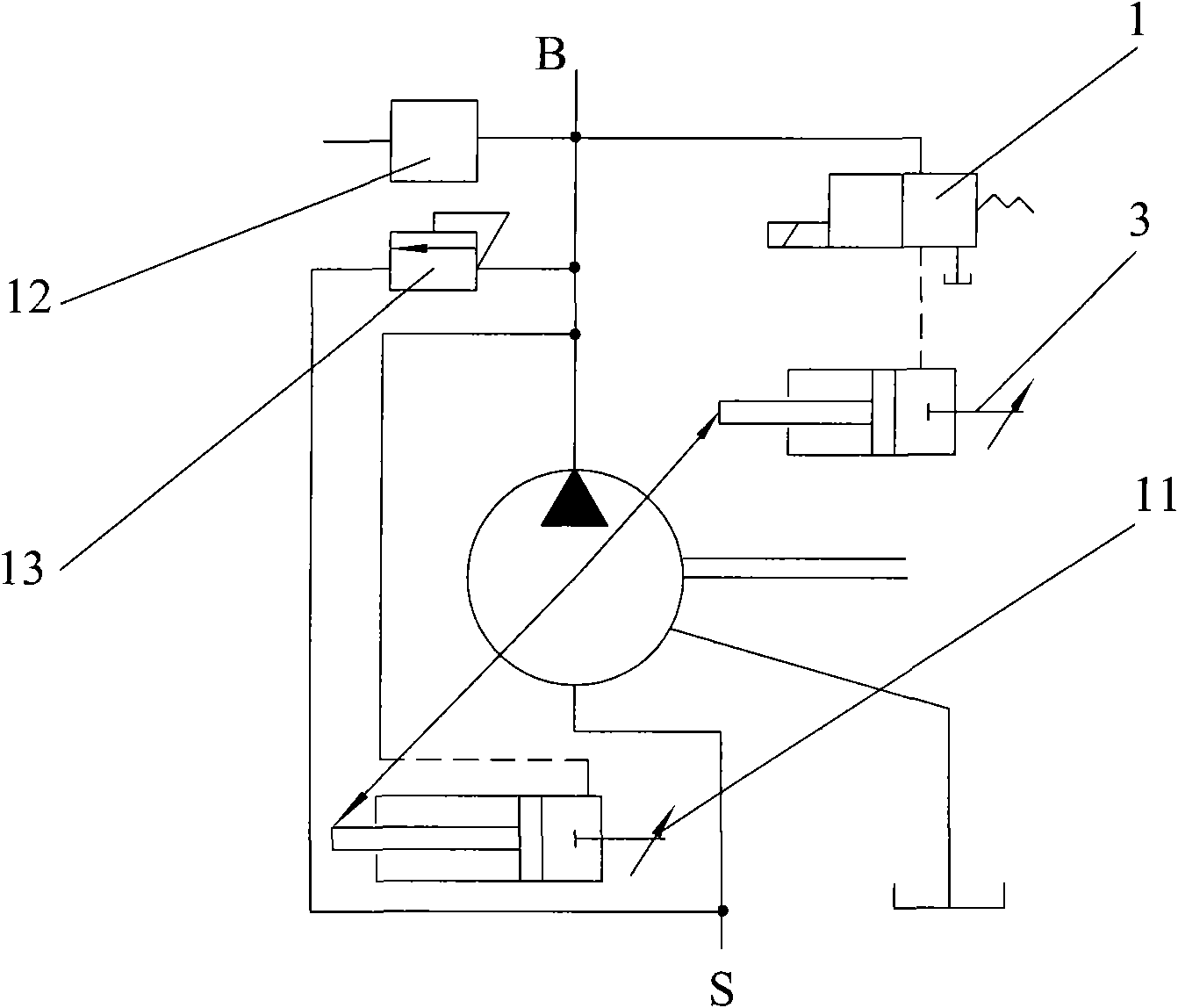
[0014] Such as figure 1 , figure 2 As shown, the plunger pump of the present invention includes: a pump casing 10, a rear cover 2, an oil outlet B, an oil inlet S, an axial hydraulic plunger machine 21, an electro-hydraulic control valve 1, and a large displacement adjustment device 3 And small displacement regulating device 11.

[0015] The pump casing 10 has an open end, on which a back cover 2 is fixed, and the side wall of the back cover 2 is also provided with an oil outlet B and an oil inlet S, and an axial hydraulic plunger machine is fixed inside the pump casing 10 21. The axial hydraulic plunger machine 21 includes: a drive shaft 9 penetrating through the side wall of the pump housing 10, the drive shaft 9 is externally connected to a servo motor, and can drive the plunger pump of the present invention to rotate by star...


PUM


Abstract

The invention discloses a plunger pump, which comprises a pump shell, a rear cover, an oil outlet, an oil inlet and an axial hydraulic plunger machine. The hydraulic plunger machine comprises a transmission shaft and a cylinder axially sleeved on the transmission shaft; one side of the cylinder is provided with nine cylinder holes; a plunger-skid shoe assembly is arranged in each cylinder hole; aswing component is movably pivoted to one side, exposed out of the cylinder hole, of the plunger-skid shoe assembly, and an oil distribution disc is fixedly arranged on the other side of the cylinder;the rear cover is parallel to the transmission shaft, and a small-displacement regulating device and a large-displacement regulating device are arranged on the rear cover and the transmission shaft symmetrically in equal distance; the small-displacement regulating device and the large-displacement regulating device penetrate the rear cover into the pump shell to be separately connected with the end margin of a swing component and flexibly adjust an included angle between the swing component and the transmission shaft through a control cylinder component; and the rear cover is also provided with an electric-hydraulic valve electrically connected with the large-displacement regulating device and a safety pressure valve. Therefore, the plunger pump has the characteristics of small vibration,stable pressure, energy saving, improvement on production efficiency, low cost and long service life.

Description

technical field [0001] The invention relates to a plunger pump, in particular to a hydraulic plunger pump used for an energy-saving power unit driven by a servo motor. Background technique [0002] An existing energy-saving power unit driven by a servo motor is mainly composed of a servo motor and a quantitative hydraulic pump. Quantitative hydraulic pumps are mainly screw pumps, gear pumps and quantitative piston pumps. Under normal working conditions, this power unit can match the flow required by the hydraulic system and control the working pressure of the system more precisely. unresolvable technical problems. If the system is in the working condition of high pressure and small flow for a long time, in order to ensure the stability of the pressure, high pressure overflow is used or the motor is kept in the state of high torque for a long time, which not only brings energy loss, but also affects the servo motor. In addition, when the system requires high-pressure and r...

Claims


Application Information

Patent Timeline
Patent Type & Authority Applications(China)
IPC IPC(8): F04B1/22
Inventor 杨小理
Owner HIGH TECH FLUID POWER CO LTD
Why Eureka
Try Eureka