Ceramic metal halide lamp shell

A metal halide and light bulb technology, applied in the field of ceramic light sources, can solve problems affecting the working efficiency and life of lamps, ceramic metal halide lamp erosion, metal halide deposition, etc., to achieve improved life, high pressure resistance, and small temperature gradient Effect

Inactive Publication Date: 2010-12-15
杨潮平
View PDF10 Cites 0 Cited by
  • Summary
  • Abstract
  • Description
  • Claims
  • Application Information

AI Technical Summary

Problems solved by technology

[0004] like figure 1 As shown, the ceramic metal halide bulb shell is composed of a discharge chamber 1 and capillary tubes 2 arranged at both ends of the discharge chamber 1. The capillary tube 2 is a straight cylindrical structure. The electrodes of this structure are sealed by filling the capillary tube 2 and the electrode rod 4 with glass solder 3. The gap is completed, so that there is a larger gap between the capillary 2 and the electrode rod 4, the larger gap will cause the halogen to enter the gap and cause losses
Moreover, in the prior art, a bell-mouth structure 5 is formed at the junction of the capillary 2 and the discharge chamber 1. This structure is easy to form a cold spot, where gold halide deposits are prone to occur, so that the halides do not all participate in the cycle, and cause its adverse effect on the metal halide. The erosion of ceramic metal halide lamps affects the working efficiency and life of the finished lamps

Method used


Image

  • Ceramic metal halide lamp shell
  • Ceramic metal halide lamp shell
  • Ceramic metal halide lamp shell

Examples


Embodiment Construction

[0031] The present invention will be described in detail below in conjunction with the embodiments and accompanying drawings.

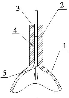
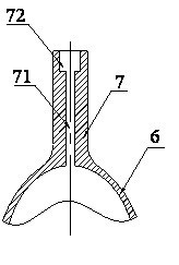
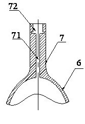
[0032] Such as figure 2 As shown, the present invention discloses a ceramic metal halide bulb shell, which includes a discharge chamber 6 and capillary tubes 7 arranged at both ends of the discharge chamber 6. The capillary tube 7 includes a connected inner tube section 71 and a welding groove 72. The inner tube section 71 is close to In the discharge chamber 6 , the welding groove 72 is located at the end surface, and the inner diameter of the welding groove 72 is larger than that of the inner pipe section 71 , and the welding groove 72 realizes the airtight sealing of the discharge chamber 6 by filling the solder 73 . In this embodiment, the inner diameter of the welding groove 72 is in the range of 1 to 4 mm, the depth is in the range of 1-4 mm, and the inner diameter of the inner pipe section is in the range of 0.4-1.5 mm.

[0033] The cold end ...


PUM

PropertyMeasurementUnit
Thicknessaaaaaaaaaa
Thicknessaaaaaaaaaa

Abstract

The invention belongs to the field of ceramic light sources, and in particular relates to a ceramic metal halide lamp shell. The ceramic metal halide lamp shell comprises a discharging cavity and capillary tubes arranged at the two ends of the discharging cavity, wherein each capillary tube comprises an inner tube section and a welding groove which are connected with each other; the inner tube section is close to the discharging cavity; the welding groove is positioned on the end face; the inside diameter of the welding groove is greater than that of the inner tube section; the welding grooverealizes air-tight seal of the discharging cavity by padding a welding flux; part of the outer surface of the discharging groove is provided with a light reflecting material layer; and a glass transparent glaze layer is covered on the outer surface, not provided with the light reflecting layer, of the discharging cavity. The ceramic metal halide lamp shell has the advantages of simple encapsulation, good sealing effect, high luminous efficiency and the like.

Description

technical field [0001] The invention belongs to the field of ceramic light sources, in particular to a ceramic metal halide bulb shell. Background technique [0002] At present, translucent alumina tubes around the world mainly have an integrated structure, a two-piece structure, a three-piece structure, or even a five-piece structure, but there is one structure that is basically the same, that is, the capillary part is a straight cylinder structure and a discharge chamber. The inner surface is basically a quadric surface structure such as a cylinder, an ellipsoid, and a sphere. [0003] In addition, the current sealing method used by ceramic metal halide lamp manufacturers is to heat the glass solder together with the ceramic tube and electrodes. The melting point of the glass solder is lower than the softening point of the ceramic, and it needs to have good fluidity after melting to penetrate In the gap between the ceramic capillary and the electrode assembly, the sealing...

Claims


Application Information

Patent Timeline
IPC IPC(8): H01J61/36H01J61/35
CPCH01J61/35H01J61/827H01J61/366
Inventor 张万镇谢灿生陆镇洲
Owner 杨潮平
Why Eureka
Try Eureka