A Centerless Fixture Used on Cylindrical Grinding Machine

A centerless fixture, cylindrical grinding machine technology, applied in grinding machines, machine tools designed for grinding workpiece rotating surfaces, manufacturing tools, etc., can solve the problems of time-consuming and laborious, high rejection rate, and inability to guarantee accuracy.

Inactive Publication Date: 2017-01-18
LIAOCHENG WANHE IND MFR
View PDF7 Cites 0 Cited by
  • Summary
  • Abstract
  • Description
  • Claims
  • Application Information

AI Technical Summary

Problems solved by technology

Since the upper punch and the lower punch used in the medicine machine are in the shape of a stepped shaft in the axial direction, when using the existing method to grind the outer circle, it is time-consuming and labor-intensive to ensure the concentricity and accuracy. Not guaranteed
The punch itself has very high requirements on the roughness of the outer surface and the coaxiality of the punch body and the punch, so in the current processing and production process, there is a problem of high scrap rate

Method used


Image

  • A Centerless Fixture Used on Cylindrical Grinding Machine
  • A Centerless Fixture Used on Cylindrical Grinding Machine
  • A Centerless Fixture Used on Cylindrical Grinding Machine

Examples


Embodiment Construction

[0016] In order to facilitate the understanding of the technical content of the present invention, the technical solutions thereof will be further described below in conjunction with the accompanying drawings. Words such as "front", "rear", "left" and "right" used in the description of the present invention are all statements based on the relationship between the drawings, and the purpose is for the convenience of description, which cannot be regarded as Restrictions on the technical content of the present invention. The terms related to "setting", "connecting" and other matching relations should be understood in a broad sense unless they are clearly defined. They can be direct fitting, indirect fitting, fixed connection, detachable connection, etc. Purpose of the present invention, understand the mode of realization.

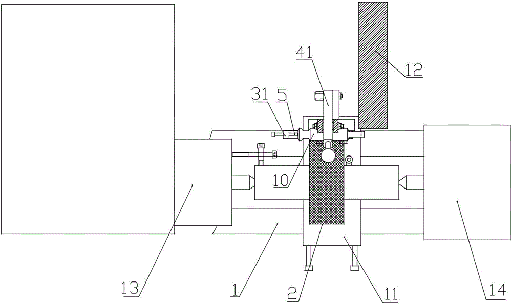
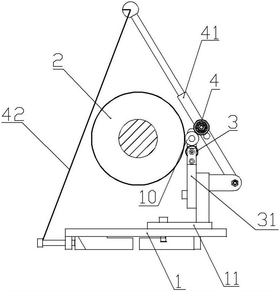
[0017] Such as Figure 2 to Figure 4 As shown, a centerless clamp used on a cylindrical grinding machine includes a driving wheel 2 installed on the rotating...


PUM


Abstract

The invention discloses a centerless fixture for a cylindrical grinding machine. The centerless fixture comprises a driving wheel, a supporting wheel and a pressing wheel, wherein the driving wheel is arranged on a rotating shaft of a grinding machine; the supporting wheel is arranged at the slanting lower part of the rear side of the driving wheel; the outer side of a support of the supporting wheel is hinged to one end of a pressing rod; the pressing wheel is arranged at the middle of the pressing rod; the other end of the pressing rod is connected with one end of a spring; the other end of the spring is connected onto a grinding machine rack; a positioning part is arranged at one end face side, which is away from a grinding wheel of the grinding machine, of the supporting wheel, on the support of the supporting wheel; a punch rod clamped among the driving wheel, the supporting wheel and the pressing wheel can be axially positioned by the positioning part; the punch rod is fixed by line contact matching between the circumferential surfaces of the driving wheel, the supporting wheel and the pressing wheel and the circumferential surface of a punch body of the punch rod; after the punch rod is fixed, the axiality of the punch rod can be directly guaranteed; the acting pressure of the pressing wheel on the punch rod is guaranteed by the pretightening force of the spring; the driving wheel is driven by the rotating shaft to rotate and drives the punch rod to rotate; the grinding processing is realized by contacting a circumferential section of the upper end to be ground of the punch rod with the grinding wheel.

Description

technical field [0001] The invention relates to the related technical field of a grinding machine fixture, in particular to a fixture used in cylindrical grinding on a cylindrical grinding machine. Background technique [0002] Such as figure 1 As shown, it is the punch rod 10 for installation on the medicine machine. The left one is a small punch tail punch, and the right one is a big punch tail punch. Their upper end is a punch head, the lower end is a punch tail, and the middle part is a punch body. , where the peripheral surface at punch A is the processing surface to be ground. At present, the outer circle of the punch rod is ground on the grinding machine by clamping one end of the punch rod on the chuck of the cylindrical grinder, and aligning it with a dial indicator to ensure the coaxiality of the punch head and the punch body of the punch rod. . Since the upper punch and the lower punch used in the medicine machine are in the shape of a stepped shaft in the axia...

Claims


Application Information

Patent Timeline
Patent Type & Authority Patents(China)
IPC IPC(8): B24B5/307
CPCB24B5/307
Inventor 康金腾庄献国刘其全耿清臣
Owner LIAOCHENG WANHE IND MFR
Why Eureka
Try Eureka