
Beam mold assembly positioning support for composite material multi-beam box section co-solidifying forming and assembly technique

A technology for positioning brackets and composite materials, which is applied in the field of beam mold assembly positioning brackets for composite multi-beam box section co-curing molding, can solve problems such as poor molding quality, shorten the manufacturing cycle, simplify the process operation, and ensure the thickness and axis. degree of effect

Active Publication Date: 2017-07-25
成都联科航空技术有限公司
View PDF2 Cites 2 Cited by
  • Summary
  • Abstract
  • Description
  • Claims
  • Application Information

AI Technical Summary

Problems solved by technology

[0010] The purpose of the present invention is to: aim at the problem of poor molding quality in the prior art, to provide a beam mold assembly positioning bracket and assembly process for co-curing molding of multi-beam box sections of composite materials; On the basis of the secondary curing and reassembly process, the beam mold is positioned and pre-assembled, thereby realizing the one-time co-curing molding of the multi-beam box section, and can guarantee the molding quality

Method used


Image

  • Beam mold assembly positioning support for composite material multi-beam box section co-solidifying forming and assembly technique
  • Beam mold assembly positioning support for composite material multi-beam box section co-solidifying forming and assembly technique
  • Beam mold assembly positioning support for composite material multi-beam box section co-solidifying forming and assembly technique

Examples


Embodiment 1

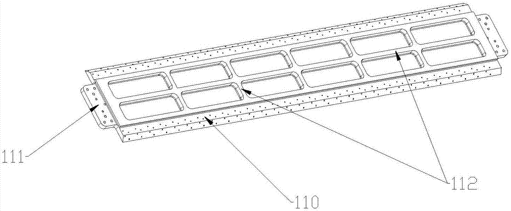
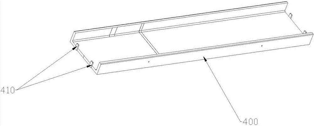
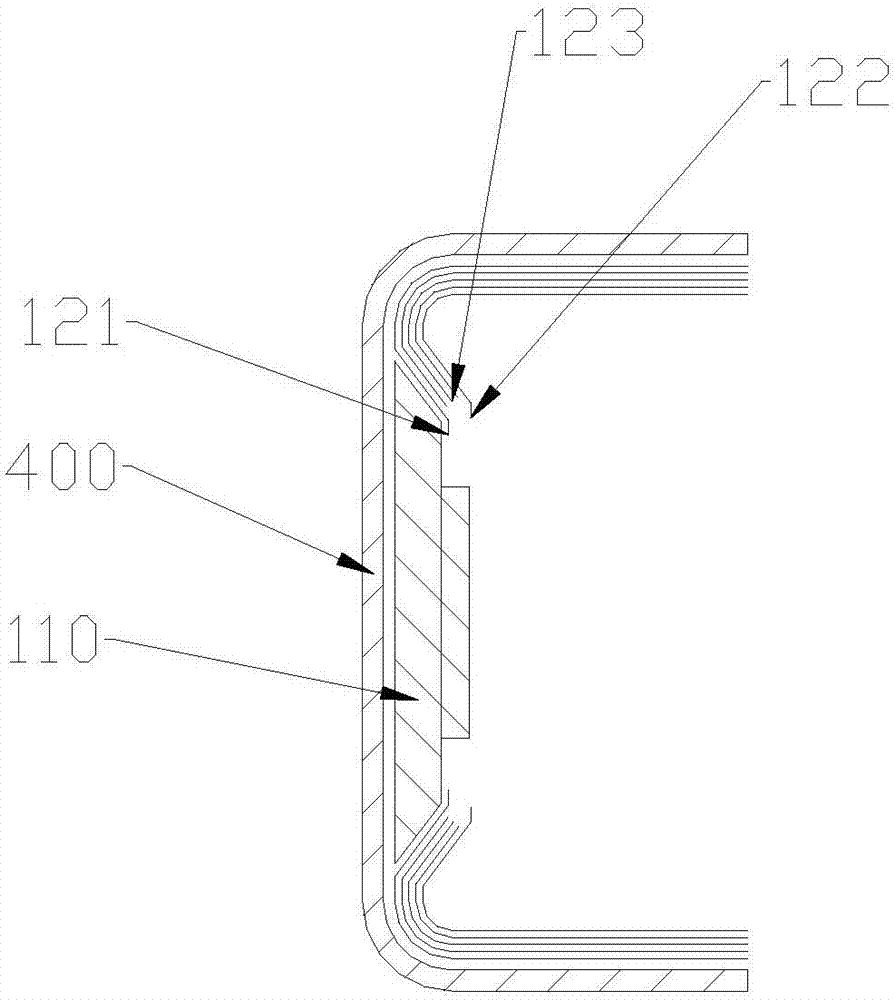
[0054] A beam mold component positioning bracket for co-curing molding of multi-beam box sections of composite materials, such as Figure 12 As shown, there are two sets of positioning brackets 300 arranged opposite to each other, and at least two sets of fixing plates 330 opposite to each other are respectively arranged on the positioning brackets 300 .

[0055] Such as Figure 12As shown, the positioning bracket 300 is provided with a positioning plate, and the positioning plate is provided with positioning pin holes. The positioning bracket 300 is composed of a crossbeam 310 and a vertical beam 320 fixed to each other, and the fixing plate 330 is arranged on the vertical beam 320 . The horizontal beam 310 and the vertical beam 320 are perpendicular to each other. There are at least two vertical beams 320 . The height of the positioning bracket 300 is smaller than the height of the beam mold assembly.

[0056] The process of using the above-mentioned composite material m...


PUM


Abstract

The invention belongs to the technical field of composite material hot pressing pot forming techniques and particularly relates to a beam mold assembly positioning support for composite material multi-beam box section co-solidifying forming and an assembly technique of a beam mold assembly. The beam mold assembly positioning support comprises two oppositely-arranged positioning support bodies, and each positioning support body is provided with at least two sets of fixing plates with the positions being opposite. According to the positioning support and the assembly technique, a beam mold is accurately positioned, one-time co-solidifying forming is achieved accordingly, and the forming quality can be ensured. Compared with the prior art, the beam mold assembly positioning support for composite material multi-beam box section co-solidifying forming and the assembly technique of the beam mold assembly have the beneficial effects that the beam mold assembly is combined, composite material multi-beam box section one-time co-solidifying forming is achieved, the purpose that accurate positioning of beam plate parts in the assembly and solidifying processes can be ensured, and thus the thicknesses and axis degrees of the parts are ensured. According to the beam mold assembly positioning support for composite material multi-beam box section co-solidifying forming and the assembly technique of the beam mold assembly, the technique is easy to operate, repeatability is high, the manufacturing period is shortened, manufacturing cost is reduced, and the weight reduction effect is achieved.

Description

technical field [0001] The invention belongs to the technical field of composite material autoclave forming technology, and in particular relates to a beam mold component positioning bracket for co-curing molding of multi-beam box sections of composite materials, and a process for assembling beam mold components using the positioning bracket. Background technique [0002] Autoclave (Hot Air Autoelave or Atitoelave for short) is a process equipment for the characteristics of polymer-based composite molding process. The method of using this equipment for molding process is called autoclave forming method. The autoclave forming method is the main method for manufacturing continuous fiber reinforced thermosetting composite parts. It is widely used in the molding of advanced composite structures, honeycomb sandwich structures and metal or composite bonded structures. When the material is formed, it is solidified by using the uniform temperature and uniform pressure provided in th...

Claims


Application Information

Patent Timeline
Patent Type & Authority Applications(China)
IPC IPC(8): B29C70/34B29C70/54B29C33/30
CPCB29C33/303B29C33/305B29C70/342B29C70/54
Inventor 张永亮李书军陈剑孙松强王雨李波成雪峰
Owner 成都联科航空技术有限公司
Learn More