Eureka AIR delivers breakthrough ideas for toughest innovation challenges, trusted by R&D personnel around the world.

A scissor-type aerial work vehicle platform lifting and lowering hydraulic system

A kind of high-altitude operating vehicle and hydraulic system technology, which is applied in the direction of lifting device, fluid pressure actuating device, servo motor, etc., and can solve problems such as large self-priming resistance, corrosion of the inner wall of the rodless cavity of the oil cylinder and piston rod, and damage to the seal. Achieve the effect of prolonging the service life and shortening the oil suction distance

Inactive Publication Date: 2016-03-23
HUNAN SINOBOOM HEAVY IND
View PDF6 Cites 0 Cited by
  • Summary
  • Abstract
  • Description
  • Claims
  • Application Information

AI Technical Summary

Problems solved by technology

[0002] Double-lift cylinder scissor-type aerial work platform usually lifts the rodless cavity and the oil circuit of the rod cavity is separated. When the platform is lowered, the hydraulic oil in the lift cylinder rodless cavity returns to the oil tank through the oil inlet hydraulic hose, and the rod The negative pressure generated in the cavity relies on the self-priming ability to absorb oil from the hydraulic oil tank. Since the scissor-type aerial work vehicle is vertically rising and falling, the higher the lifting height, the greater the self-priming resistance, and the worse the self-priming ability, resulting in the lifting of the cylinder. The rod cavity produces air suction, which will damage the seals. At the same time, the water in the sucked air will cause the inner wall of the rodless cavity of the cylinder and the piston rod to rust
When using emergency descent, the operation is cumbersome and needs to pull two spools at the same time

Method used


Image

  • A scissor-type aerial work vehicle platform lifting and lowering hydraulic system
  • A scissor-type aerial work vehicle platform lifting and lowering hydraulic system

Examples


Embodiment Construction

[0011] The present invention will be further described below in conjunction with the accompanying drawings and specific embodiments.

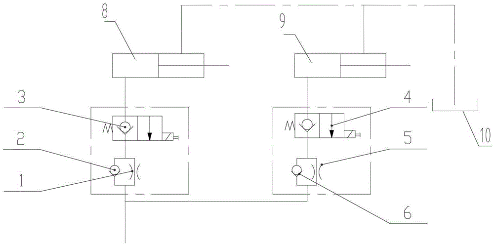
[0012] see figure 1 , the existing hydraulic system includes the first throttle valve 1, the second throttle valve 5, the first one-way valve 2, the second one-way valve 6, the first two-position two-way electromagnetic reversing valve with manual function 3, the second Two-position two-way electromagnetic reversing valve 4 with manual function, upper lifting oil cylinder 8, lower lifting oil cylinder 9 and oil tank 10. When the scissor lift is lifted, the pressure oil passes through the first one-way valve 2 and the second one-way valve respectively. The directional valve 6 enters the upper and lower lifting cylinders respectively through the first two-position two-way electromagnetic directional valve 3 with manual function and the second two-position two-way electromagnetic directional valve 4 with manual function, the upper lifting oil cyli...


PUM


Abstract

The invention discloses a lifting and dropping action hydraulic system for scissor type aerial working trolley platforms. The outlet of a first one-way valve (2) is connected with the rodless cavity of a lower lifting oil cylinder (9) and a first hand-operable two-position two-way electromagnetic reversing valve (3), the first hand-operable two-position two-way electromagnetic reversing valve (3) is connected with one end of a first throttle valve (1), the rod cavity of the lower lifting oil cylinder (9) and the other end of the first throttle valve (1) are connected with an oil tank (10), the outlet of a second one-way valve (6) is connected with the rodless cavity of an upper lifting oil cylinder (8) and the inlet of a two-position two-way electromagnetic reversing valve (11), the outlet of the two-position two-way electromagnetic reversing valve (11) is connected with one end of a second throttle valve (5), the rod cavity of the upper lifting oil cylinder (8) and the other end of the second throttle valve (5) are connected with the oil tank (10), and an overflow valve (7) is connected between the rodless cavity of the upper lifting oil cylinder (8) and the oil tank (10). Hydraulic oil is always filled up in the rod cavities of the lifting oil cylinders of the lifting and dropping action hydraulic system, consequently, seals in the oil cylinders are protected, the service lives of the oil cylinders are prolonged, and emergency dropping operation is simple.

Description

technical field [0001] The invention relates to a high-altitude operation vehicle, in particular to a scissor-type high-altitude operation equipment (double-lift cylinder high-altitude operation platform) working platform ascending and descending hydraulic system. Background technique [0002] Double-lift cylinder scissor-type aerial work platform usually lifts the rodless cavity and the oil circuit of the rod cavity is separated. When the platform is lowered, the hydraulic oil in the lift cylinder rodless cavity returns to the oil tank through the oil inlet hydraulic hose, and the rod The negative pressure generated in the cavity relies on the self-priming ability to absorb oil from the hydraulic oil tank. Since the scissor-type aerial work vehicle is vertically rising and falling, the higher the lifting height, the greater the self-priming resistance, and the worse the self-priming ability, resulting in the lifting of the cylinder. The rod cavity produces air suction, whic...

Claims


Application Information

Patent Timeline
Patent Type & Authority Patents(China)
IPC IPC(8): F15B11/08F15B13/02B66F11/04
Inventor 岳奇
Owner HUNAN SINOBOOM HEAVY IND
Why Eureka
Eureka Blog
Learn More