Eureka AIR delivers breakthrough ideas for toughest innovation challenges, trusted by R&D personnel around the world.

Road cleaning vehicle and its suction nozzle

A technology for cleaning vehicles and roads, applied in the field of sanitation machinery, can solve the problems of garbage leakage, inability to be absorbed by any suction port, leakage, etc., and achieve the effect of shortening the suction distance and improving the efficiency and effect of garbage suction

Active Publication Date: 2016-05-18
ZOOMLION ENVIRONMENTAL IND CO LTD
View PDF5 Cites 0 Cited by
  • Summary
  • Abstract
  • Description
  • Claims
  • Application Information

AI Technical Summary

Problems solved by technology

figure 1 and figure 2 The existing suction nozzle is shown, and the suction nozzle has a suction nozzle cavity 9 with an open lower part, and the suction nozzle cavity 9 includes an upper sealing plate 7 at the top, and the side surfaces respectively connected to the upper sealing plate 7 along the width direction. Plate 4 and the front baffle 3 and the rear baffle 5 that are respectively connected to the front side and rear side of the upper sealing plate 7, two spaced air guiding tubes 13 are formed on the upper sealing plate 7, and each air guiding tube 13 A suction port 10 is formed in the center, and the two suction ports 10 are respectively communicated with the suction device for sucking the garbage in the cavity 9 of the suction nozzle, wherein the front baffle 3 has flexibility and is formed into a straight plate type, and this structure sucks There is a garbage leakage phenomenon in the area between the two nozzles 10. Specifically, when the road cleaning vehicle is operating, due to the symmetry of the nozzle structure, the flow field in the nozzle cavity is symmetrically distributed, causing the movement to the middle of the nozzle. The trash is subjected to the suction force of the same size and opposite direction of the suction ports on both sides, the resultant force tends to be balanced or small, and cannot be absorbed by any suction port, resulting in leakage

Method used


Image

  • Road cleaning vehicle and its suction nozzle
  • Road cleaning vehicle and its suction nozzle
  • Road cleaning vehicle and its suction nozzle

Examples


Embodiment Construction

[0033] Specific embodiments of the present invention will be described in detail below in conjunction with the accompanying drawings. It should be understood that the specific embodiments described here are only used to illustrate and explain the present invention, and are not intended to limit the present invention.

[0034] In the present invention, the orientation words used such as "vertical, horizontal", "up, down", "left, right" and "front, back" are usually used in the context provided by the invention unless stated otherwise. The mouth is defined under normal use and is also consistent with the directions shown in the drawings; "inner and outer" refer to the inner and outer relative to the outline of each component itself.

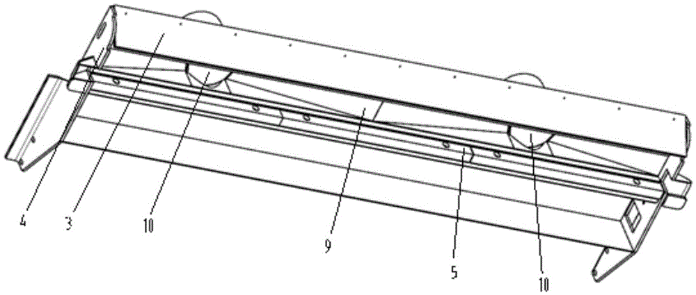
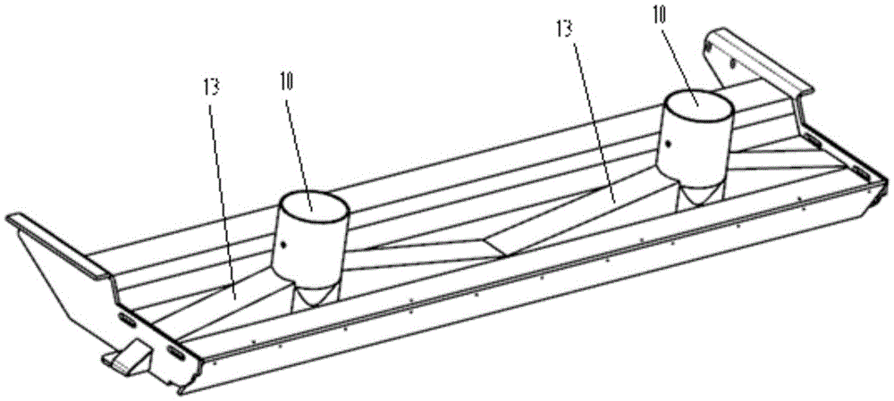
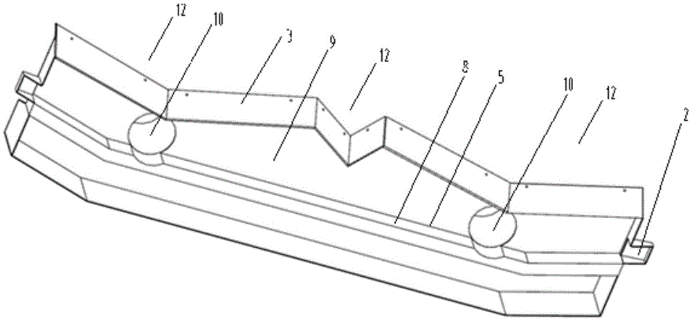
[0035] The present invention provides a suction nozzle, the suction nozzle has a suction nozzle cavity 9 with an open bottom, and the suction nozzle cavity 9 includes an upper sealing plate 7 at the top, which is respectively connected to the upper...


PUM


Abstract

The invention discloses a road cleaner and a suction nozzle thereof. The suction nozzle is provided with a suction nozzle cavity (9) with an open lower portion, the suction nozzle cavity (9) comprises an upper sealing plate (7) located at the top, side plates (4) connected to the left side and the right side of the upper sealing plate (7) respectively in the width direction of the suction nozzle, a front baffle (3) and a rear baffle (5), wherein the front baffle (3) and the rear baffle (5) are connected to the front side and the rear side of the upper sealing plate (7) respectively, the front baffle (3) is flexible, two suction openings (10) which are arranged at intervals in the width direction of the suction nozzle are formed in the upper sealing plate (7), the front baffle (3), in the width direction of the suction nozzle, comprises three connected V-shaped sections (12), and the middle V-shaped section (12) corresponds to the position between the two suction openings (10). The suction nozzle has good rubbish suction efficiency and a good suction effect.

Description

technical field [0001] The invention relates to the field of sanitation machinery, in particular to a road cleaning vehicle and its suction nozzle. Background technique [0002] Road cleaning vehicles (such as washing and sweeping vehicles) are common sanitation machinery used for road cleaning. During the working process of the road cleaning vehicle, the garbage on the road surface is swept into the lower part of the chassis by means of the sweeping brush, and then the garbage enters the nozzle space of the suction nozzle. Cavity 9, the garbage enters the suction port 10 under the action of negative pressure in the cavity of the suction nozzle and is driven by the airflow to finally enter the dustbin. figure 1 and figure 2 The existing suction nozzle is shown, and the suction nozzle has a suction nozzle cavity 9 with an open lower part, and the suction nozzle cavity 9 includes an upper sealing plate 7 at the top, and the side surfaces respectively connected to the upper s...

Claims


Application Information

Patent Timeline
Patent Type & Authority Patents(China)
IPC IPC(8): E01H1/08
Inventor 徐浩覃先云伍乾坤
Owner ZOOMLION ENVIRONMENTAL IND CO LTD
Why Eureka
Eureka Blog
Learn More