An on-orbit calibration method for image plane errors of six degrees of freedom for star sensors

A technology of star sensor and calibration method, which is applied in the directions of instruments, measuring devices, astronomical navigation, etc., can solve the problems of six-degree-of-freedom image plane error, satellite attitude determination error, satellite star sensor image plane error, etc., and achieve attitude determination. The effect of improving the accuracy, improving the control accuracy, and eliminating the image plane error of the star sensor

Active Publication Date: 2016-01-20
HARBIN INST OF TECH
View PDF3 Cites 0 Cited by
  • Summary
  • Abstract
  • Description
  • Claims
  • Application Information

AI Technical Summary

Problems solved by technology

[0003] The present invention aims to solve the problem that the image plane error of the star sensor caused by the harsh space working environment and the vibration of the satellite itself in the existing star sensor will cause a relatively large error in the determination of the satellite attitude, and proposes a six-freedom star sensor On-orbit Calibration Method of Image Plane Error

Method used


Image

  • An on-orbit calibration method for image plane errors of six degrees of freedom for star sensors
  • An on-orbit calibration method for image plane errors of six degrees of freedom for star sensors
  • An on-orbit calibration method for image plane errors of six degrees of freedom for star sensors

Examples


specific Embodiment approach 2

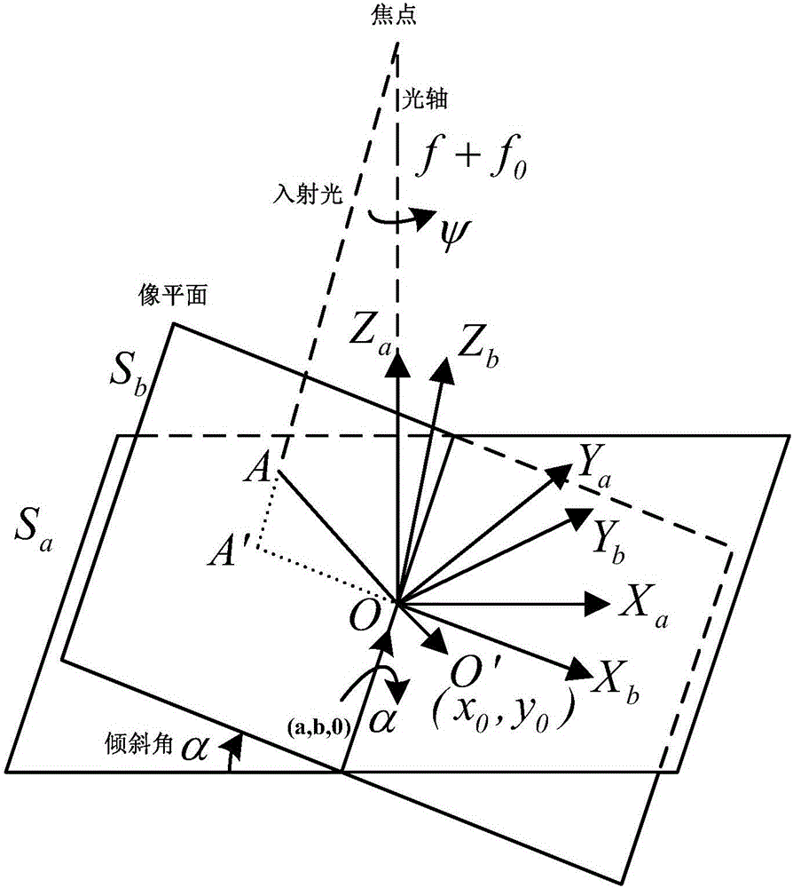
[0026] Specific embodiment two: this embodiment is a further description of specific embodiment one, the star sensor in step one obtains the imaging point coordinates (x, y, f) under the star sensor coordinate system to the target star imaging, where x , y are the coordinates of the imaging point in the x and y directions, and f is the focal length of the star sensor lens.

specific Embodiment approach 3

[0027] Specific embodiment three: This embodiment is a further description of specific embodiment one. In step two, the error coefficient and error correction formula in the six-degree-of-freedom image plane error model of the star sensor are introduced, wherein the star sensor six-degree-of-freedom image plane The error coefficient is (a,α,ψ,x 0 ,y 0 , f 0 ), the original size of the error coefficient is obtained through ground experiments; the correction formula for the six-degree-of-freedom image plane error of the star sensor is:

[0028] x ′ = f + f 0 f + f 0 - ...

specific Embodiment approach 4

[0031] Embodiment 4: This embodiment is a further description of Embodiment 1. In step 3, the coordinates of the imaging point of the target star after error correction are converted into the unit direction vector W of the target star in the star sensor coordinate system, specifically The expression is as follows:

[0032] W = 1 x ′ 2 + y ′ 2 + ( f - f 0 ) 2 - x ′ ...


PUM


Abstract

The invention relates to an on-orbit calibration method for a six-degree-of-freedom image plane error of a star sensor. The on-orbit calibration method is used for solving the problem that a larger error is generated due to the image plane error of an existing star sensor during the satellite attitude determination. The on-orbit calibration method is realized according to the following steps: imaging a target fixed star by utilizing the star sensor; introducing an error coefficient and an error correction formula in a six-degree-of-freedom image plane error model; converting an imaging point coordinate of the target fixed star which is subjected to the error correction into a unit direction vector of the target fixed star in a star sensor coordinate system; acquiring the unit direction vector of the target fixed star in an inertial system; counting angular distances among num target fixed stars and differential coefficients of the angular distances to a six-degree-of-freedom image plane error coefficient of the star sensor, so as to obtain an intermediate computing matrix; carrying out iterative computation on an evaluated error variance matrix to obtain the real six-degree-of-freedom image plane error coefficient of the star sensor. The on-orbit calibration method is applied to the technical field of the satellite attitude determination.

Description

technical field [0001] The invention relates to the technical field of satellite attitude determination, in particular to an on-orbit calibration method for a six-degree-of-freedom image plane error of a star sensor. Background technique [0002] Among various satellite attitude sensors, star sensors have the highest attitude determination accuracy. With the further exploration of space, higher requirements are placed on satellite attitude determination and control accuracy. Therefore, star sensors are used in satellite attitude determination. The system is used more and more. However, the image plane of the star sensor will be seriously deformed after working for a long time in the harsh space working environment. In addition, the vibration of the satellite will cause the image plane of the star sensor to change in real time, resulting in the existing star sensor. The error coefficients considered in the image plane error model of the star sensor are few, and the attitude ...

Claims


Application Information

Patent Timeline
Patent Type & Authority Patents(China)
IPC IPC(8): G01C25/00G01C21/02
Inventor 孙亚辉耿云海胡芳芳方向肖盈莹李诚良
Owner HARBIN INST OF TECH
Why Eureka
Try Eureka