Magnetorheological brake

A brake and magneto-rheological technology, applied in the direction of brake types, liquid resistance brakes, mechanical equipment, etc., can solve the problems of non-adjustable braking force, poor heat dissipation, and non-adjustable braking force, etc., to improve safety performance and reliability, braking The effect of dynamic continuation

Inactive Publication Date: 2013-12-18
CHINA UNIV OF MINING & TECH
View PDF5 Cites 23 Cited by
  • Summary
  • Abstract
  • Description
  • Claims
  • Application Information

AI Technical Summary

Problems solved by technology

[0003] As an application branch of magnetorheological fluid, magnetorheological brake has the characteristics of fast brake response, less wear of brake parts, large braking torque, simple control, small vibration, and low control energy consumption. It is an ideal The brake device can avoid the problems of traditional brakes such as complex control, bulky, expensive, insufficient braking torque, and poor heat dissipation
At present, there are many application examples and patent documents of magneto-rheological brakes. For example, the Chinese invention patent with the publication number CN101225859A disclosed "a magneto-rheological brake" on July 23, 2008. The brake uses permanent magnets as the magnetic source. The magnetic field can be continuously generated, but its braking force cannot be adjusted; the Chinese invention patent with the publication number CN102146968A disclosed "a multi-disk magneto-rheological brake" on August 10, 2011. The excitation coil of the brake is easy to disassemble, but it cannot be realized Power-off braking function
Therefore, it can be seen that there is a shortcoming in the existing magneto-rheological brakes, that is, the excitation coil or the permanent magnet is used for the magnetic supply mode alone, and the permanent magnet magnetic supply is safe, but the braking force cannot be adjusted; Power failure or coil failure will cause interruption of braking force, poor safety and reliability

Method used


Image

  • Magnetorheological brake

Examples


Embodiment Construction

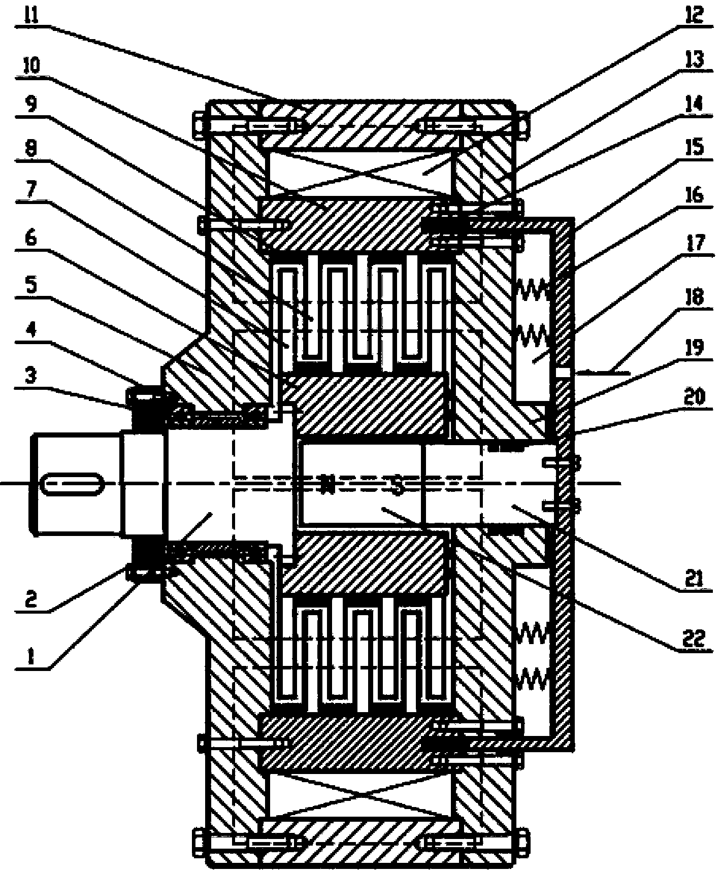
[0012] The present invention will be further described below in conjunction with the accompanying drawings.

[0013] Such as figure 1 As shown, the magneto-rheological brake includes a brake shaft 1, a left magnetic shell 5, a right magnetic shell and a middle magnetic shell 11, the brake shaft 1 is installed on the brake axis through a bearing 3, and the two bearings 3 pass through the bearing The retaining ring 4 is separated and installed and fixed by the end cover 2. The middle magnetic shell 11 is fixed between the left magnetic shell 5 and the right magnetic shell by bolts, and the left magnetic shell 5 and the right magnetic shell are connected to each other by bolts respectively. The outer magnetic isolation shell 10 with inner splines is fixedly connected, and the excitation coil 12 is installed in the space formed by the middle magnetic conduction shell 11, the left magnetic conduction shell 5, the outer magnetic isolation shell 10 and the right magnetic conduction s...


PUM


Abstract

The invention discloses a magnetorheological brake and belongs to the technical field of mechanical brake. A magnetism-conducting ring (14) is arranged in an annular slot of an outer magnetism-isolating shell (10), and a magnetism-isolating cup (15) is arranged in an annular through slot of a right magnetism-conducting shell; a sliding magnetism-conducting shaft (21) and a permanent magnet (22) are inserted in circular holes of a right magnetism-conducting shell II (19) and an inner magnetism-isolating shell (6), and the magnetism-isolating cup and the sliding magnetism-conducting shaft are connected; an extension spring group (16) is arranged in a sealed cavity (17) formed by the magnetism-isolating cup and the right magnetism-conducting shell II, and a pressure oil inlet (18) is formed in the magnetism-isolating cup. The magnetorheological brake disclosed by the invention realizes magnetism supply brake to provide controllable power by utilizing a magnet exciting coil under normal operation conditions; when the magnet exciting coil breaks down or powers off, a magnetism supply brake mode of the magnet exciting coil is quickly converted to a magnetism supply brake mode of the permanent magnet under the action of the extension spring group and the pressure oil in the sealed cavity, so that the continuity of the braking force of the magnetorheological brake is ensured, and the safety and the reliability of the magnetorheological brake are improved.

Description

technical field [0001] The invention relates to a magneto-rheological brake, belonging to the technical field of mechanical brakes. Background technique [0002] Magnetorheological fluid is a kind of particle suspension, mainly composed of soft magnetic particles, base carrier liquid and additives wrapped on the particle surface. Because there are soft magnetic particles in magnetorheological fluid, which are sensitive to magnetic field, it is a kind of intelligent magnetic functional material. Under the action of magnetic field, magnetorheological fluid will have obvious rheological effect, and the soft magnetic particles will appear The chain structure is arranged to form numerous particle chains, and the particle chains will hinder the free flow of the carrier fluid, making the magnetorheological fluid behave as a semi-solid macroscopically, and present a certain shear yield stress. Due to its unique magnetorheological properties, since the advent of magnetorheological f...

Claims


Application Information

Patent Timeline
IPC IPC(8): F16D57/00
Inventor 田祖织吴向凡陈飞
Owner CHINA UNIV OF MINING & TECH
Why Eureka
Try Eureka