Variable frequency speed regulating disk type motor and vacuum pump

A disc motor, frequency control technology, applied in the direction of magnetic circuit shape/style/structure, winding conductor shape/style/structure, magnetic circuit static parts, etc., can solve the limitation of the use range of vacuum pumps, frequency control motors Unable to adapt to use requirements, unstable load capacity and other problems, to achieve the effect of improving electrical performance and starting performance, good low-frequency and low-speed operation characteristics, and improving power factor and efficiency

CN103457366AActive Publication Date: 2013-12-18北京富特盘式电机有限公司
6 Cites 5 Cited by

Patent Information

Authority / Receiving Office
CN · China
Patent Type
Applications(China)
Current Assignee / Owner
Publication Date
2013-12-18

Smart Images

  • Figure 1
    Figure 1
  • Figure 2
    Figure 2
  • Figure 3
    Figure 3
Patent Text Reader

Abstract

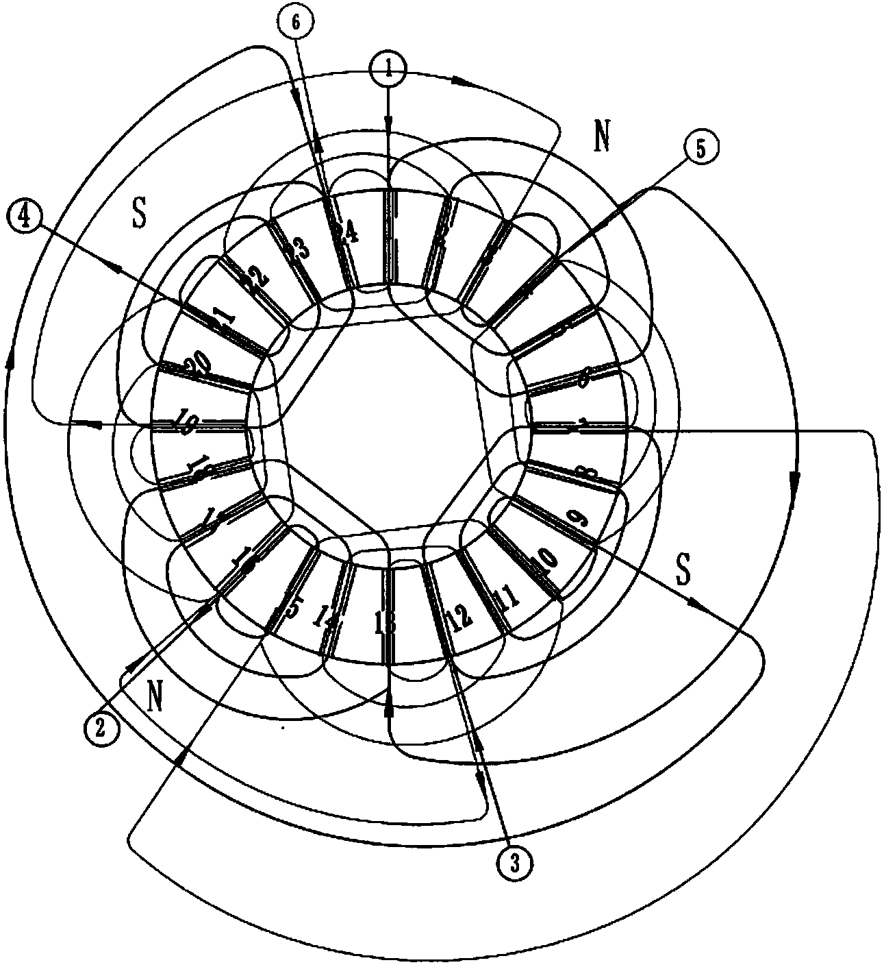
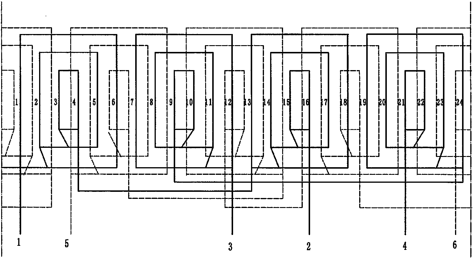
The invention provides a variable frequency speed regulating disk type motor which uses sinusoidal windings and is in a double-layered type. Through interactive compensation action of two coils in each electrode of two main windings, the electrodes are sequentially connected, a magnetic filed is made to be distributed more evenly, the waveform is close to the sine wave, and declining of torque can not happen any more at a low rotating speed. Meanwhile, in the starting process, an auxiliary winding is connected with an operating capacitor and a starting capacitor, in the operating process, the auxiliary winding and the operating capacitor are connected, and startability and overload capacity are guaranteed. Meanwhile, through switching of the connecting mode of a high voltage and a low voltage, when the motor works in the high voltage of 200V-240V, the first main winding and the second main winding are in parallel connection with an auxiliary winding circuit after being in series connection, and when the motor works in the low voltage of 100V-120V, the first main winding, the second main winding and the auxiliary winding circuit are in mutual parallel connection. The variable frequency speed regulating disk type motor meets the operating demands in different rotating speed range under a general voltage condition in the global range. In addition, integration of the motor and a pump is achieved when the variable frequency speed regulating disk type motor is applied to a vacuum pump.
Need to check novelty before this filing date? Find Prior Art

Description

technical field

[0001] The invention relates to the technical field of motors, in particular to a frequency-variable speed-regulating disc motor for a vacuum pump and a vacuum pump using the motor. Background technique

[0002] The existing variable frequency speed regulating motor for vacuum pumps is structurally assembled separately from the vacuum pump, and is independent of each other. Due to high energy consumption during operation and the inability to meet the operating requirements of low-speed and low-frequency working conditions of 100V-120V and 200 rpm, the loss of torque at low speeds is severely reduced, the load capacity is not stable during operation, and the efficiency is obvious. Reduced, thus unable to meet the requirements of the vacuum pump running at low frequency and low speed. At the same time, the existing variable-frequency speed-regulating motor cannot meet the requirements of different voltage and frequency standards in different countries and regi...

Examples

Embodiment Construction

[0028] The technical solution of the present invention will be described in detail below in conjunction with the accompanying drawings, so that those skilled in the art can understand the solution of the present invention more clearly, but the protection scope of the present invention is not limited thereby.

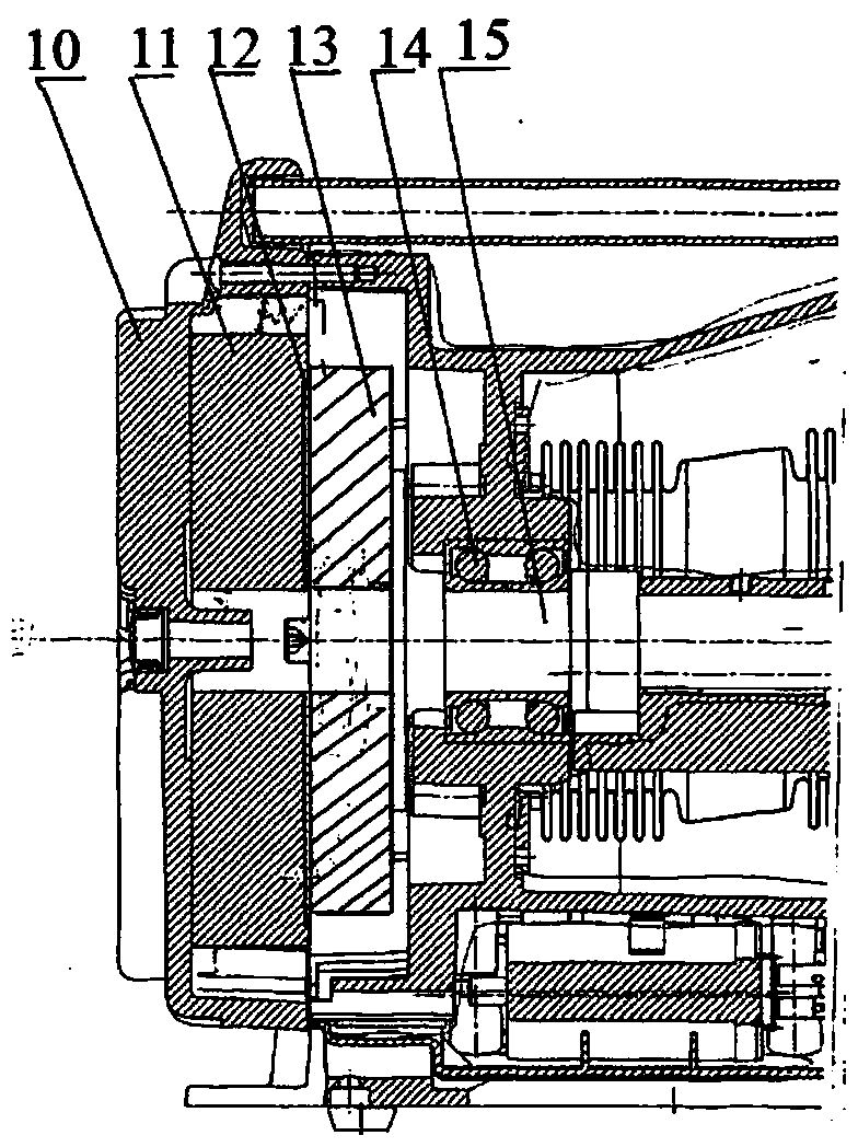
[0029] as attached figure 1 As shown, the frequency conversion speed regulating disc motor of the present invention includes a flat disc-shaped stator 11 and a rotor 13, and the described motor can be applied to a vacuum pump, and its installation in the vacuum pump is as follows: figure 1 As shown, the stator 11 and rotor 13 are directly embedded in the vacuum pump housing 10 for assembly, the air gap 12 between the stator and rotor can be adjusted, and the rotor 13 is a cast aluminum squirrel-cage rotor in a radial shape, and is fixedly installed On the transmission shaft 15 of the vacuum pump, the transmission shaft 15 is connected to the housing 10 through the bearin...