Servo power cutter head

A milling head and power technology, which is applied in the direction of driving devices, automatic lathes/semi-automatic lathes, turning equipment, etc., can solve problems such as difficult conversion, difficult conversion links, cumbersome procedures, etc., to achieve extended service life, stable operation, and reduced noise effect

Active Publication Date: 2014-01-08
丹东富田精工机械有限公司
View PDF7 Cites 1 Cited by
  • Summary
  • Abstract
  • Description
  • Claims
  • Application Information

AI Technical Summary

Problems solved by technology

[0002] Existing parts processing generally needs to go through multiple processes such as turning, milling, planing, grinding, etc. Different processes are processed by different machine tools, and the machine tools must be converted. The conversion of machine tools is not only cumbersome, but also increases the labor intensity of workers. It is difficult, and it is inevitable to bump and scratch the processing surface, which will affect the processing accuracy, especially for small workpieces with high precision requirements, and it is not easy to convert
And milling is generally carried out by vertical milling machines, horizontal milling machines, universal milling machines and special gear milling equipment, but these equipment are relatively professional and limited by size specifications, it is difficult to complete the milling of some small workpieces

Method used


Image

  • Servo power cutter head
  • Servo power cutter head

Examples


Embodiment

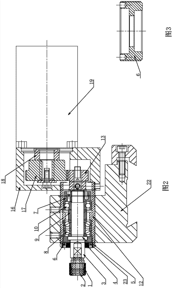
[0023] Example: such as figure 1 As shown, the present invention includes a servo motor 19, a gear box 16, first and second gears 13, 17 that cooperate with each other, a main shaft 3, a shaft housing 12 and a main shaft seat 20, and the main shaft seat 20 is fixed on the On the lathe tool rest 22, the main shaft 3 is installed on one end of the main shaft seat 20 through its shaft shell 12, and the collet 2 and the first nut 1 are installed on the working end of the main shaft 3 for adornment of the tool, and the other end is installed with the second nut 15 The first gear 13 and the second gear 17 matched with it are mounted on the output shaft end of the servo motor 19, and the gear box 16 is sleeved outside the two gears and connected with the motor housing and the main shaft housing 12 respectively. Wherein the first nut 1 and the collet 2 are purchased parts.

[0024] In this example, the main shaft 3 and its shaft housing 12 are connected through the first and second b...

Embodiment 2

[0029] Embodiment 2: as figure 2 As shown, the difference between this example and Example 1 is that the first and second gears 13 and 17 in this example are both spur gears, the shafts of the two gears are parallel to each other, and the gear ratio is 1:2.


PUM


Abstract

A servo power cutter head comprises a servo motor, a gear case, a first gear, a second gear, a main shaft, a shaft shell and a main shaft base, wherein the first gear is matched with the second gear. The main shaft base is fixed on a lathe carriage, the main shaft is installed at one end of the main shaft base through the shaft shell, the working end of the main shaft is provided with a cutter, the other end of the main shaft is provided with the first gear, the second gear matched with the first gear is installed at the output shaft end of the servo motor, the two gears are sleeved with the gear case which is respectively connected with a motor outer shell and the main shaft shell. The servo power cutter head can be installed on a lathe, and in the process of turning, milling, drilling and taping are achieved. A shaft seal device is arranged between the working end of the main shaft and the shaft shell, cutting oil, chippings and the like can be effectively prevented from entering the main shaft, and a bearing of the main shaft is prevented from being abraded and scrapped. The main shaft can operate stably, and the service life of the bearing of the main shaft is prolonged. The height of the main shaft is adjusted by adjusting two shaft shell adjusting nuts, and height fine adjustment is achieved. A bearing thrust nut and a thrust locking nut are used for preventing the main shaft from floating axially and for locking the bearing.

Description

technical field [0001] The invention belongs to the technical field of machining, in particular to a servo power milling head. Background technique [0002] Existing parts processing generally needs to go through multiple processes such as turning, milling, planing, grinding, etc. Different processes are processed by different machine tools, and the machine tools must be converted. The conversion of machine tools is not only cumbersome, but also increases the labor intensity of workers. It is difficult, and it is inevitable to bump and scratch the processing surface, which will affect the processing accuracy, especially for small workpieces with high precision requirements, and it is not easy to change. And milling is generally carried out by vertical milling machines, horizontal milling machines, universal milling machines and special gear milling equipment, but these equipment are relatively professional and limited by size specifications, it is difficult to complete the m...

Claims


Application Information

Patent Timeline
Patent Type & Authority Applications(China)
IPC IPC(8): B23Q5/10B23B11/00
CPCB23Q1/70B23Q5/10
Inventor 田川
Owner 丹东富田精工机械有限公司
Why Eureka
Try Eureka