Ball joint three-dimensional shaft

A ball joint, three-dimensional technology, applied in the field of ball joint transmission mechanism, to achieve the effect of strong practical value, ingenious mechanism and simple structure

Inactive Publication Date: 2014-02-05
SHENYANG POLYTECHNIC UNIV
View PDF5 Cites 2 Cited by
  • Summary
  • Abstract
  • Description
  • Claims
  • Application Information

AI Technical Summary

Problems solved by technology

To solve the problem of converting three-dimensional

Method used


Image

  • Ball joint three-dimensional shaft
  • Ball joint three-dimensional shaft
  • Ball joint three-dimensional shaft

Examples


Embodiment Construction

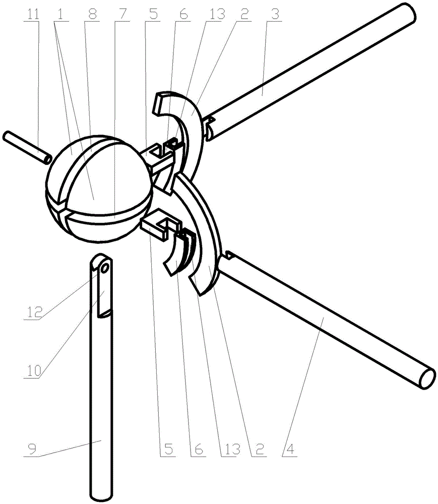
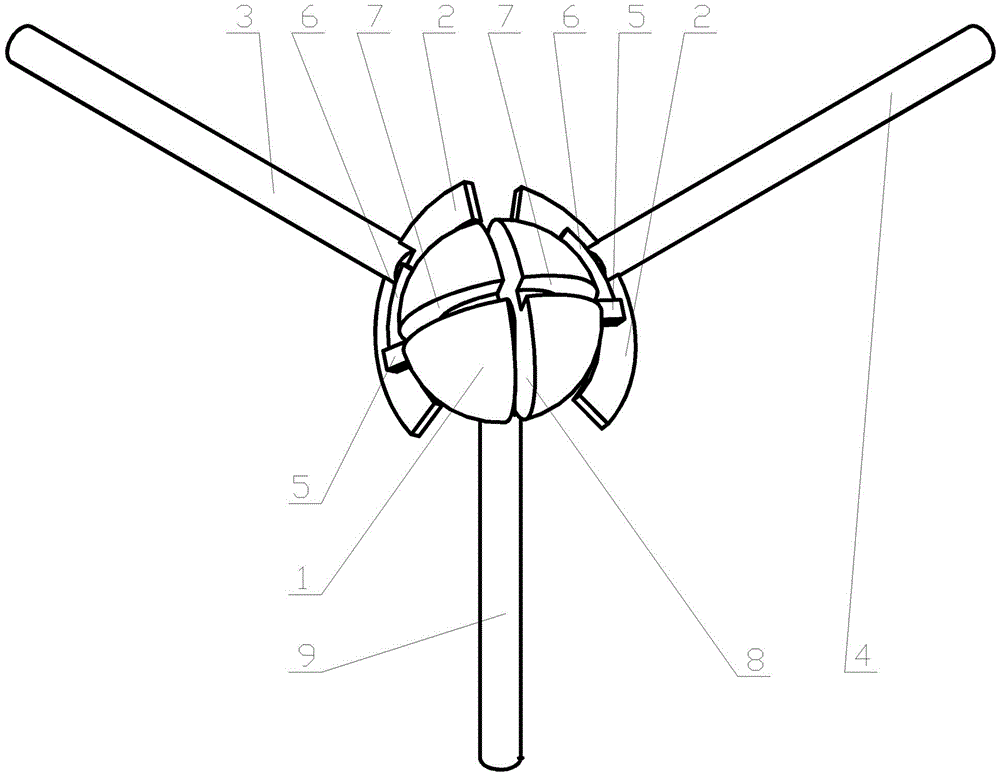
[0024] exist Figure 1 to Figure 4 Among them, it represents the structural composition of the present invention and the connection and positional relationship of the parts. The three-dimensional axis of the ball joint includes a ball 1, a slider 5, a moving slideway 6, a slider 2, an X axis 4, a Y axis 3, a Z axis 9 and Pin 11; sphere 1 is provided with Z-axis chute 8 and XY-axis chute 7, Z-axis chute 8 and XY-axis chute 7 are square grooves, 360 degrees are distributed on sphere 1, Z-axis chute 8 The position is vertically placed, the position of the XY axis chute 7 is perpendicular to the Z axis chute 8; the Z axis 9 is placed vertically, the upper end of the Z axis 9 is set as the Z axis slider head 10, and the two The side surface is in contact with the two sides of the Z-axis chute 8 on the sphere 1 and forms a clearance fit; a pin hole 12 is provided in the XY-axis chute 7 and on the Z-axis slider head 10, and a pin 11 is inserted into the pin hole 12. The pin 11 is fi...


PUM


Abstract

The invention provides a ball joint three-dimensional shaft. The ball joint three-dimensional shaft comprises a ball body, a slide block, a movable slide rail, slide strips, an X shaft, a Y shaft, a Z shaft and a pin, wherein the ball body is provided with a Z shaft slide groove and an XY shaft slide groove vertical to the Z shaft slide groove; and the ball body and the Z shaft can rotate relatively around the pin. The Z shaft, the X shaft and the Y shaft are vertical to one another; the X shaft and the Y shaft are placed horizontally and can only rotate around respective axes; the slide strips are fixedly connected with a connection end between the X shaft and the ball body and a connection end between the Y shaft and the ball body; the movable slide rail is internally provided with an arc-shaped slide groove; the two side faces of the slide strips are contacted with the two side faces of the arc-shaped slide groove to form clearance fit; the slide strips slide in the arc-shaped slide groove; the two side faces of the slide block are contacted with the two side faces of the XY shaft slide groove on the ball body to form the clearance fit; and the slide block can slide in the XY shaft slide groove. According to the ball joint three-dimensional shaft, one ball joint is rotated to drive the three mutually-vertical shafts to rotate so as to immediately and accurately decompose a space corner to each vertical shaft and realize the effect of converting a space three-dimensional corner into a plane two-dimensional corner. The ball joint three-dimensional shaft is simple in structure and ingenious in mechanism and has stronger practical value.

Description

technical field [0001] The invention relates to a ball joint transmission mechanism, in particular to a ball joint three-dimensional shaft in which three mutually perpendicular axes rotate simultaneously through the rotation of the ball joint. Background technique [0002] In the mechanical transmission mechanism, the universal joint is a common mechanism that connects two shafts to achieve coaxial or different shaft transmission, but the universal joint cannot be used in the occasion where the two shafts are perpendicular, let alone the In the case of connecting three mutually perpendicular axes. In practical applications, there are many occasions where one joint rotation is required to simultaneously drive three mutually perpendicular axes to rotate at the same time. The problem of angle decomposition of space Cartesian coordinate system, the problem of projection transformation of space straight line and plane to three projection planes in mechanical drawing, etc. Adopt...

Claims


Application Information

Patent Timeline
IPC IPC(8): F16D3/16
Inventor 孙学雁郭辉程大鹏赵琳王云龙李响
Owner SHENYANG POLYTECHNIC UNIV
Why Eureka
Try Eureka