Gravity compensation method for flexible follow-up control of spacecraft manipulator

A technology of gravity compensation and mechanical arm, applied in manipulators, manufacturing tools, etc., can solve the problems of manual installation of parts and components, difficult to control the installation accuracy, difficult to manually install parts and other problems, and achieve the effect of solving the problem of gravity compensation.

Inactive Publication Date: 2016-10-05
BEIJING INST OF SPACECRAFT ENVIRONMENT ENG
View PDF4 Cites 0 Cited by
  • Summary
  • Abstract
  • Description
  • Claims
  • Application Information

AI Technical Summary

Problems solved by technology

This assembly method has certain limitations. It is difficult to manually install large-size and heavy-weight parts, and it is difficult to manually install parts in a small space. For parts that require high installation accuracy, manual installation is difficult to control the installation accuracy.

Method used


Image

  • Gravity compensation method for flexible follow-up control of spacecraft manipulator
  • Gravity compensation method for flexible follow-up control of spacecraft manipulator
  • Gravity compensation method for flexible follow-up control of spacecraft manipulator

Examples


Embodiment approach 1

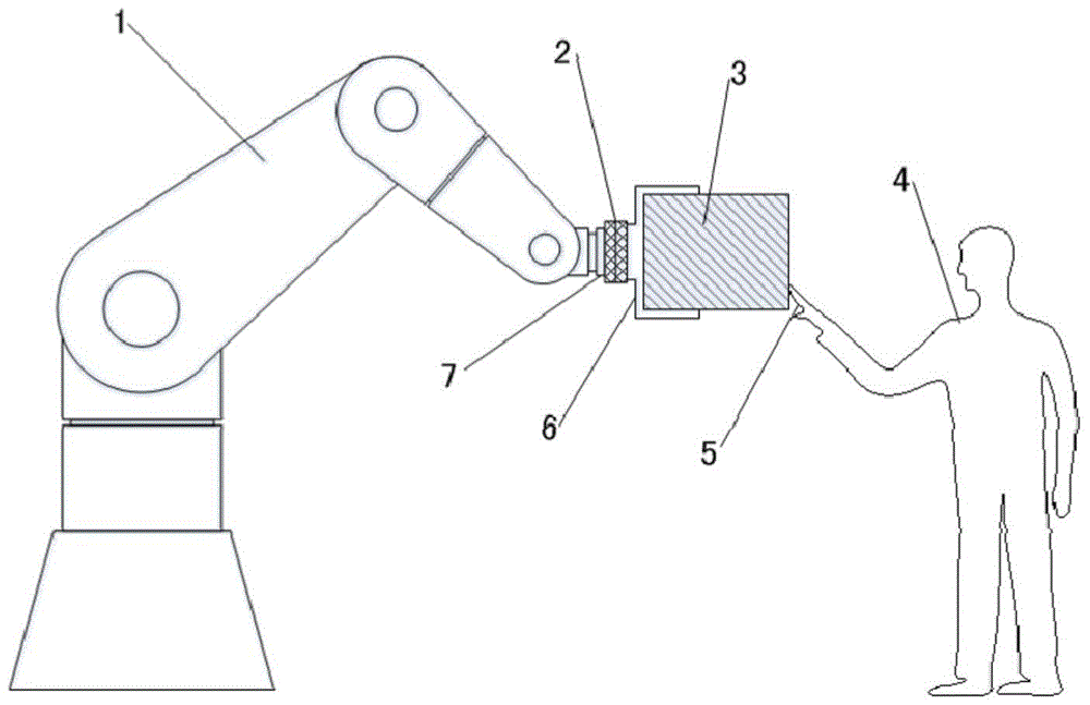
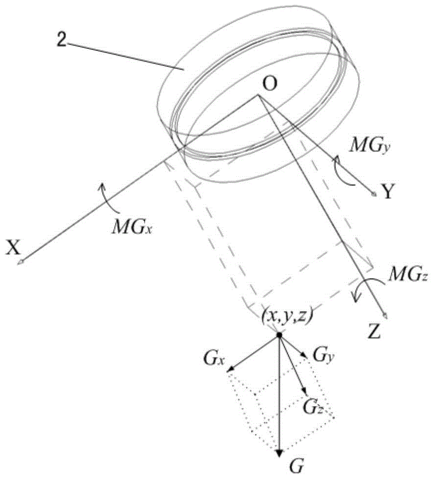
[0031] like figure 1 As shown, in the robotic arm flexible follow-up control system used in the gravity compensation method of the present invention, the six-dimensional force sensor 2 is installed between the end flange 7 of the robotic arm 1 and the fixture 6, and the six-dimensional force sensor is an industry-leading Well-known and mature sensor products, which are easy to buy (such as ATI's six-dimensional force sensor), are clamped by the operating part 3 and clamp 6, and the operating part 3 and the clamp 6 together constitute the load of the six-dimensional force sensor 2 , the load gravity is G, the direction is vertical downward, the operator 4 pushes the operated part 3 with his hand 5, and the force exerted on the operated part is Fh.

[0032] The force and torque information detected by the six-dimensional force sensor 2 is the result of the joint action of the load gravity G and the force Fh of the hand 5. To realize the flexible follow-up control of the robot ar...

Embodiment approach 2

[0048] The difference between the present embodiment and the first embodiment lies in the calculation method of the load gravity G and the coordinates of the center of gravity (x, y, z).

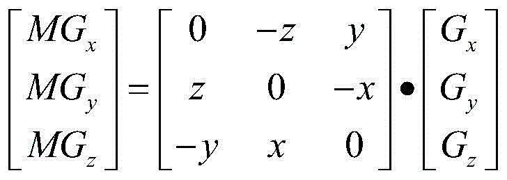
[0049] When the end of the fixed robot arm 1 is in any posture, and the load has no external force, the force components measured by the six-dimensional force sensor 2 are Fx0, Fy0, Fz0, and the moment components are Mx0, My0, Mz0, then:

[0050] Mx0=Fz0×y-Fy0×z

[0051] My0=Fx0×z-Fz0×x

[0052] Mz0=Fy0×x-Fx0×y

[0053] Adjust the posture of the end of the robot arm 1 so that the Y axis of the coordinate system of the six-dimensional force sensor 2 points to the direction of gravity. At this time, when the load has no external force, the force components measured by the six-dimensional force sensor 2 are Fx1, Fy1, Fz1 , the moment components are Mx1, My1, Mz1, which also satisfy:

[0054] Mx1=Fz1×y-Fy1×z

[0055] My1=Fx1×z-Fz1×x

[0056] Mz1=Fy1×x-Fx1×y

[0057] Since the Y-axis of the...


PUM


Abstract

The invention discloses a gravity compensation method for the flexible follow-up control of a spacecraft manipulator. In the flexible follow-up control, a six-dimensional force sensor is arranged between the end of the manipulator and the load. The method controls the manipulator so that the load is at multiple For different space attitudes, when the load has no external force, record the measurement data of the six-dimensional force sensor under each space attitude, and calculate the gravity of the load G and the center of gravity of the load from the measurement data according to the physical relationship between force and moment. Coordinates; and compensate the effect of gravity according to the force of the load. The method of the present invention uses the manipulator system itself to measure the gravity of the load and the position of the center of gravity, and the designed algorithm calculates the gravity compensation values ​​of the six components measured by the six-dimensional force sensor, which solves the problem of gravity compensation in the flexible follow-up control of the manipulator .

Description

technical field [0001] The invention belongs to the technical field of control of robotic arms, and in particular, the invention relates to a method for compensating load gravity in flexible follow-up control of robotic arms. Background technique [0002] The development of spacecraft is characterized by a single piece and small batches. The current assembly operations rely heavily on manual operations, supplemented by simple tools such as spreaders, lift trucks, and ladders to assemble different spacecraft. This assembly method has certain limitations. It is difficult to manually install large-size and heavy-weight components, and it is difficult to manually install components in a narrow space. For components that require high installation accuracy, manual installation is difficult to control the installation accuracy. . [0003] In order to solve the assembly problem of spacecraft under complex working conditions and improve assembly quality, assembly efficiency and safe...

Claims


Application Information

Patent Timeline
Patent Type & Authority Patents(China)
IPC IPC(8): B25J13/08
Inventor 刘宏阳傅浩卫月娥张立建胡瑞钦唐赖颖易旺民万毕乐孙继鹏布仁孙刚张成立郭静然
Owner BEIJING INST OF SPACECRAFT ENVIRONMENT ENG
Why Eureka
Try Eureka