Gravity Compensation Device for Space Manipulator with Two Swivel Arms Separately Used

A space manipulator, gravity compensation technology, applied in manipulators, simulation devices of space navigation conditions, transportation and packaging, etc., can solve the problem of no six-degree-of-freedom space manipulator, achieve good scalability, small deformation influence, The arm of the gravity compensation device is subject to the effect of low torque

Active Publication Date: 2016-01-20
HARBIN INST OF TECH
View PDF7 Cites 0 Cited by
  • Summary
  • Abstract
  • Description
  • Claims
  • Application Information

AI Technical Summary

Problems solved by technology

[0004] In summary, there is currently no gravity compensation system for six-degree-of-freedom space manipulators to perform space simulation experiments on the ground

Method used


Image

  • Gravity Compensation Device for Space Manipulator with Two Swivel Arms Separately Used
  • Gravity Compensation Device for Space Manipulator with Two Swivel Arms Separately Used
  • Gravity Compensation Device for Space Manipulator with Two Swivel Arms Separately Used

Examples


specific Embodiment approach 1

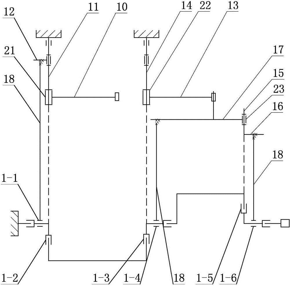
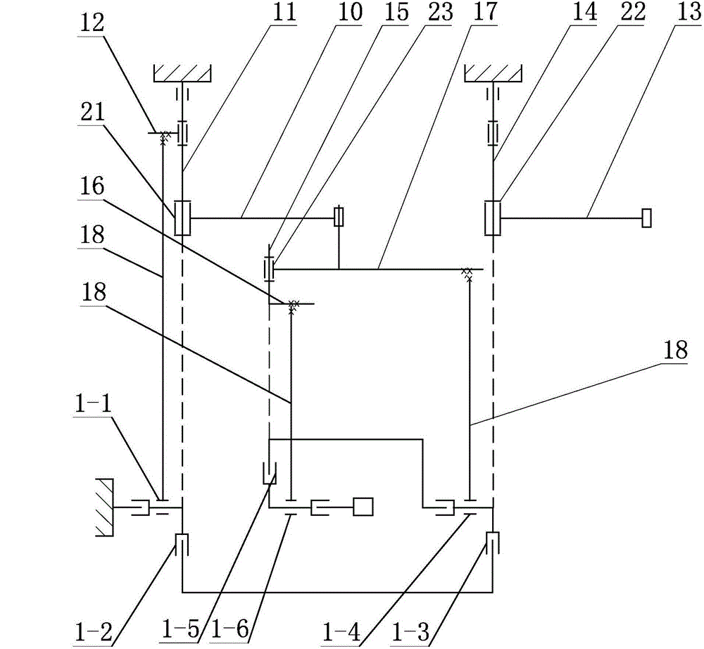
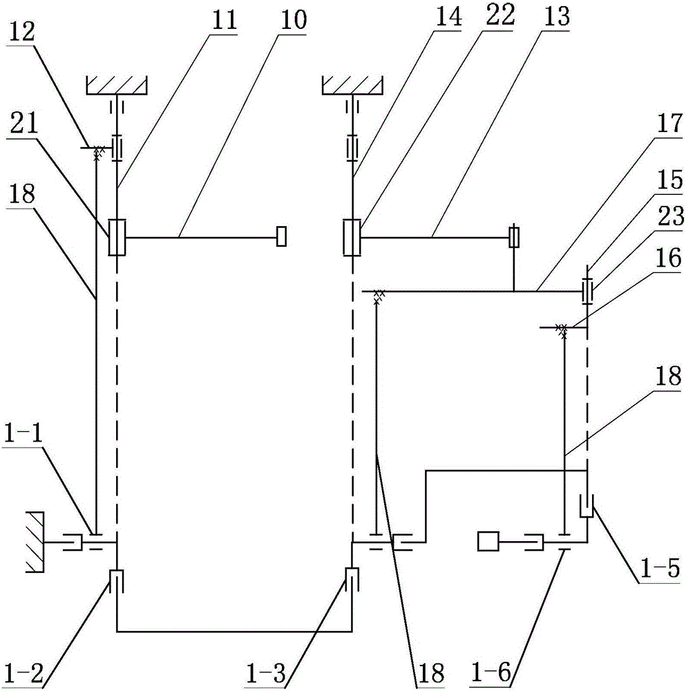
[0018] Specific implementation mode one: as Figure 1~4 As shown, the space manipulator gravity compensation device with two slewing arms used alone in this embodiment includes a main slewing system, a large slewing system and three sets of boom counterweight systems 18;

[0019] The main rotary system includes a main rotary arm 10, a main rotary shaft 11 and a forearm 12, the main rotary shaft 11 is vertically arranged and coaxially arranged with the first joint 1-2 of the space manipulator, and the upper end of the main rotary shaft 11 is fixed On the first frame, the main rotating arm 10 is arranged horizontally, and one end of the main rotating arm 10 is rotationally connected with the lower part of the main rotating shaft 11. ;

[0020] The large rotary system includes a large rotary arm 13 and a large rotary shaft 14, the large rotary shaft 14 is vertically arranged and coaxially arranged with the second joint 1-3 of the space manipulator, and the upper end of the large...

specific Embodiment approach 2

[0024] Specific implementation mode two: as figure 1 and Figure 4 As shown, the suspension rod counterweight system 18 of this embodiment includes a suspension rod 20-1, a fixed pulley 20-2 and a counterweight 20-3, and the other end of the small arm 12, the double-slewing suspension clip 17 and the small swing arm 16 A fixed pulley 20-2 is installed, and a suspension rod 20-1 is installed on each fixed pulley 20-2, and one end of the suspension rod 20-1 is connected with a counterweight 20-3, and the other end of the suspension rod 20-1 One end is connected with the corresponding link of the space manipulator. With such a design, the structure is simple, and it is convenient to adjust the counterweight of each lifting point, which provides convenience for gravity compensation. Other components and connections are the same as those in the first embodiment.

specific Embodiment approach 3

[0025] Specific implementation mode three: as figure 1 As shown, the gravity compensation device in this embodiment also includes a first bushing 21, the first bushing 21 is set on the main rotary shaft 11, and one end of the main rotary arm 10 is fixed on the outer wall of the first bushing 21 superior. In this design, the structure is simple and the structural space is compact. The first bushing 21 fixes the boom counterweight system 18 to the main rotary shaft 11, and the lower end of the boom counterweight system 18 is connected to the space manipulator, which can make the space manipulator and the space manipulator The movement of the main rotary axis 11 is synchronized so that gravity compensation can be achieved. Other compositions and connections are the same as those in Embodiment 1 or 2.


PUM


Abstract

The invention discloses a space manipulator gravity compensation device capable of independently using two revolving arms and relates to a gravity compensation device. The problem that a gravity compensation system of a space manipulator which is used for carrying out a space simulation experiment on the ground does not exist is solved. A rotating shaft is vertically arranged and is coaxially arranged with a first joint of the space manipulator; the upper end of the main rotating shaft is fixed to a first rack; one end of a main rotating arm is rotatably connected with the lower part of the main rotating shaft; one end of a small arm is fixedly connected to the middle of the main rotating shaft; a big rotating shaft is vertically arranged and is coaxially arranged with a second joint of the space manipulator; the upper end of the big rotating shaft is fixed to a second rack; one end of a big rotating arm is rotatably connected with the lower part of the big rotating shaft; a small rotating shaft is mounted at one end of a double rotating suspension clamp; the small rotating shaft is rotatably connected with the double rotating suspension clamp; the small rotating shaft is vertically arranged and is coaxially arranged with a third joint of the space manipulator; one end of a small rotating arm is fixedly connected to the lower end of the small rotating shaft. The space manipulator gravity compensation device capable of independently using two revolving arms can be used for the space manipulator to carry out the space simulation experiment on the ground.

Description

technical field [0001] The invention relates to a gravity compensation device for a space manipulator, in particular to a gravity compensation device for a space manipulator with two slewing arms for ground testing. Background technique [0002] The six-degree-of-freedom space manipulator subsystem is an important part of the space robot system. In the laboratory development stage, the functional verification and kinematic algorithm verification of the robotic arm should be carried out. The installation of the robotic arm and the satellite body should be realized in the final assembly yard. After installation, the function of the robotic arm and the motion accuracy of the testing robotic arm should be verified. The above process must be completed on the ground, and the mechanical arm is designed according to the requirements of the weightless environment in space. In the ground test, if gravity compensation is not performed, the effect of gravity will generate large forces a...

Claims


Application Information

Patent Timeline
Patent Type & Authority Patents(China)
IPC IPC(8): B25J19/00B64G7/00
Inventor 刘振高海波邓宗全丁亮李楠路达
Owner HARBIN INST OF TECH
Why Eureka
Try Eureka