Fully hydraulic reverse circulation drilling machine

A reverse circulation, full hydraulic technology, applied in the direction of drill bits, drill pipes, drill pipes, etc., can solve problems such as unstable movement, high equipment cost, and impact on drilling speed

Inactive Publication Date: 2015-11-18
王乐康
View PDF15 Cites 13 Cited by
  • Summary
  • Abstract
  • Description
  • Claims
  • Application Information

AI Technical Summary

Problems solved by technology

However, there are the following disadvantages: 1. High equipment cost: the most widely used rotary drilling rig with a construction diameter of 1.5 to 2 meters and a drilling depth of 40 meters costs more than 4 million yuan.
Although it is widely used in the market, it also has the following disadvantages: 1. The power head is noisy, the movement is not stable, and the equipment is unstable during operation.
2. The sealing effect of the mud pump and the reduction box is poor, and the operation is difficult when the drilling depth is more than 100
3. Due to the poor sealing effect, it takes a long time to evacuate the drill pipe during the drilling operation, so that the operation time is long
4. The drilling pressure of the drill bit comes from the weight of the mud pump, reduction box, drill pipe and drill bit. Therefore, when encountering hard rock formations, dense pebble layers, and boulder layers, the pressure cannot be forced, which will seriously affect the drilling. speed, can't even work
5. It is more difficult to construct in hard rock formations, denser pebble formations, and boulder formations (reference: market forecast and development ideas for rotary drilling rigs; Chinese patent, patent number ZL03260475.0, drilling rigs)

Method used


Image

  • Fully hydraulic reverse circulation drilling machine
  • Fully hydraulic reverse circulation drilling machine
  • Fully hydraulic reverse circulation drilling machine

Examples


Embodiment 1

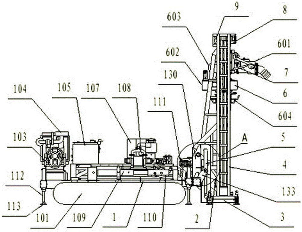
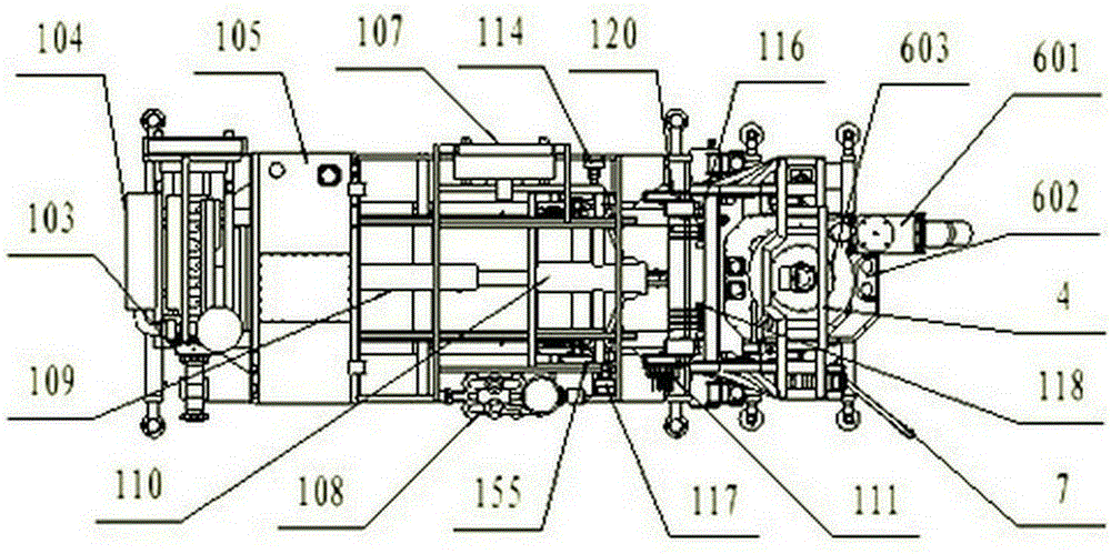
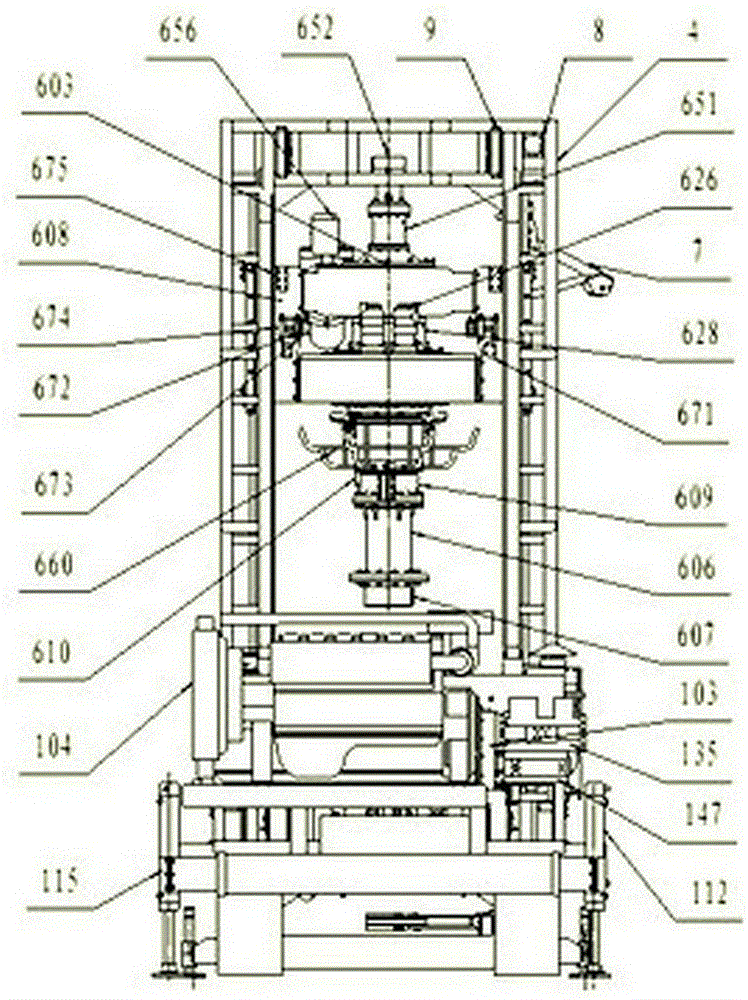
[0307] Example 1 A fully hydraulic reverse circulation drilling rig, including a traveling mechanism 101, a chassis assembly 1, two lower pulley assemblies 2, a workbench assembly 3, a main frame 4, two main frame turning cylinders 5, a swing rod assembly 7, a hinge Car assembly 8, two upper pulley assemblies 9 ( Figure 1-4 ), cylinder pulley assembly 110, drill pipe 13 ( Figure 78-79 ), remover 16 ( Figures 116-118 ),Hydraulic system( Figure 120 ); also includes power take-off assembly 103 ( Figure 22-24 ), impact drill 14 ( Figures 80-88 ), rotor bit 15 ( Figure 89-114 ), the power assembly (referred to as the power assembly) 6 and the cylinder pulley assembly 110 containing the swivel joint assembly;

[0308] Walking mechanism 101 Welded under the chassis assembly 1, it adopts vehicle-mounted self-propelled mechanism or crawler self-propelled mechanism to adapt to different working environments;

[0309] Chassis component 1 It is a welded assembly, and th...


PUM


Abstract

The invention provides a fully hydraulic reverse circulation drilling machine, which comprises a walking mechanism, a chassis assembly, a work table frame assembly, a main frame, a main frame turning oil cylinder, a swinging rod assembly, a winch assembly, a drill pipe, a dismounting device, a hydraulic system, a power take-off assembly, an impact drill bit, a rotating wing drill bit, a power assembly and an oil cylinder pulley assembly. A diesel engine or electric power is used for driving; hydraulic motors and oil cylinders are used as executing mechanisms; and the whole process operation of the drilling machine is realized through a hydraulic transmission and control system. The two hydraulic motors and a gear reducer are used for forming a power head to drive a drilling tool to rotate; the hydraulic motors adopt a serial connection or parallel connection mode; and the drill pipe realizes different rotating speeds and can adapt to different-geological-condition and different-hole-diameter operations. The oil cylinders are used for controlling the oil pipe feeding and lifting the drilling tool, so that the power head can vertically move along with the drilling tool and can realize floating, suspension stop and pressurized drilling; the drill pipe can be automatically dismounted and mounted; and the impact drill bit and the rotating wing drill bit are used for realizing the hole drilling of holes with the hole diameter being 2 to 3m and the hole depth exceeding 200m in the pebble bed, the hard rock stratum and the stratum containing large-diameter rock blocks.

Description

technical field [0001] The invention belongs to the technical field of hole-forming construction machinery, and in particular relates to a full hydraulic reverse circulation drilling machine. Background technique [0002] At present, the hole-forming construction machines widely used in the market include rotary drilling rigs and 8JH-80 series reverse circulation drilling rigs. [0003] Rotary drilling rig is a construction machine suitable for hole-forming operations in building foundation engineering. However, there are following disadvantages: 1. High equipment cost: the most widely used rotary drilling rig with a construction diameter of 1.5 to 2 meters and a drilling depth of 40 meters costs more than 4 million yuan. If the construction caliber is larger, the price of a drilling rig plus accessories will be tens of millions of yuan. 2. The volume of the equipment is both large and heavy: a set of equipment generally reaches tens of tons or even hundreds of tons, and t...

Claims


Application Information

Patent Timeline
Patent Type & Authority Applications(China)
IPC IPC(8): E21B7/02E21B4/16E21B15/00E21B19/18E21B10/43E21B10/36
Inventor 王乐康于文付志成杨晓东
Owner 王乐康
Why Eureka
Try Eureka