Pneumatic rotatable glass cutting machine

A cutting machine and glass technology, applied in glass cutting devices, glass manufacturing equipment, manufacturing tools, etc., can solve the problems of expanding the processing range of special-shaped glass cutting machines, difficult to increase the cutting speed, and the knife is not fast enough to raise labor productivity. , The equipment control system is simple and cost-saving

Inactive Publication Date: 2014-03-05
史国罕
View PDF6 Cites 1 Cited by
  • Summary
  • Abstract
  • Description
  • Claims
  • Application Information

AI Technical Summary

Problems solved by technology

The glass cutting machine adopts a second motor on the knife holder, and controls the turning of the knife wheel through the second motor. After the workpiece is positioned, the second motor controls the knife wheel to automatically adjust to the cutting position for cutting. There is no need to use this cutting machine for cutting. The pre-cutting process expands the processing range of the special-shaped glass cutting machine; however, the glass cutting machine mainly relies on the ball screw to move the knife up and down, so it is necessary to add a device for measuring the thickness of the glass. According to this data, the falling knife is not accurate enough, and it is easy to crush the glass; the lifting knife is not fast enough, making it difficult to increase the cutting speed

Method used


Image

  • Pneumatic rotatable glass cutting machine
  • Pneumatic rotatable glass cutting machine
  • Pneumatic rotatable glass cutting machine

Examples


Embodiment Construction

[0020] The present invention will be further described below in conjunction with accompanying drawing and by specific embodiment:

[0021] see Figure 2 to Figure 7 :

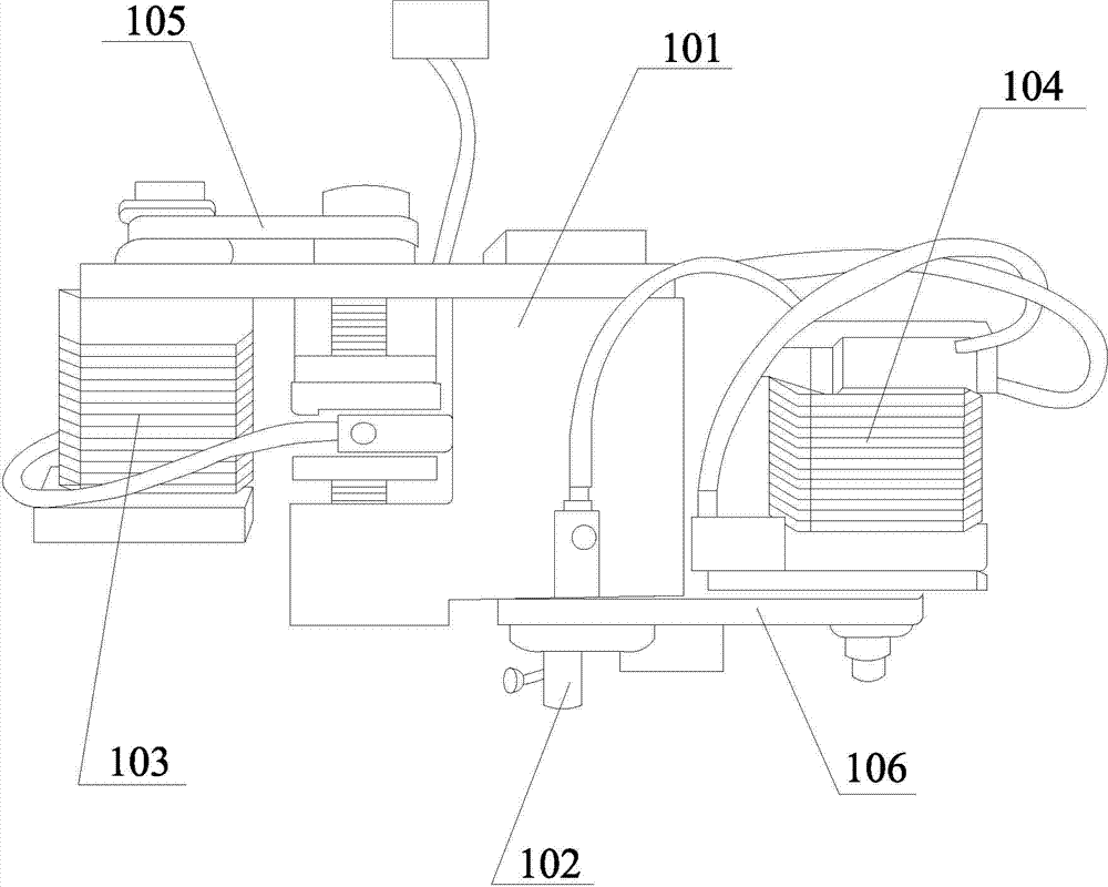
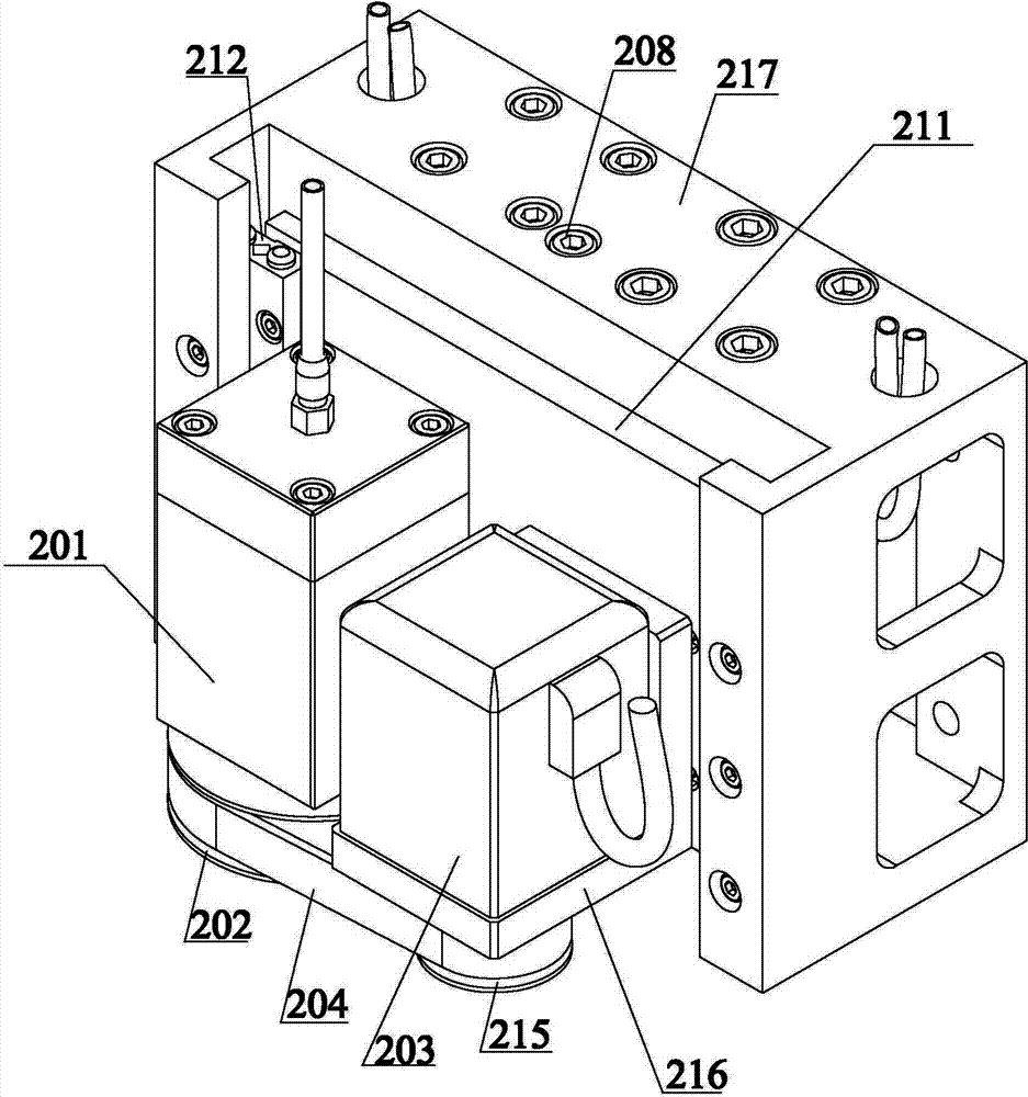
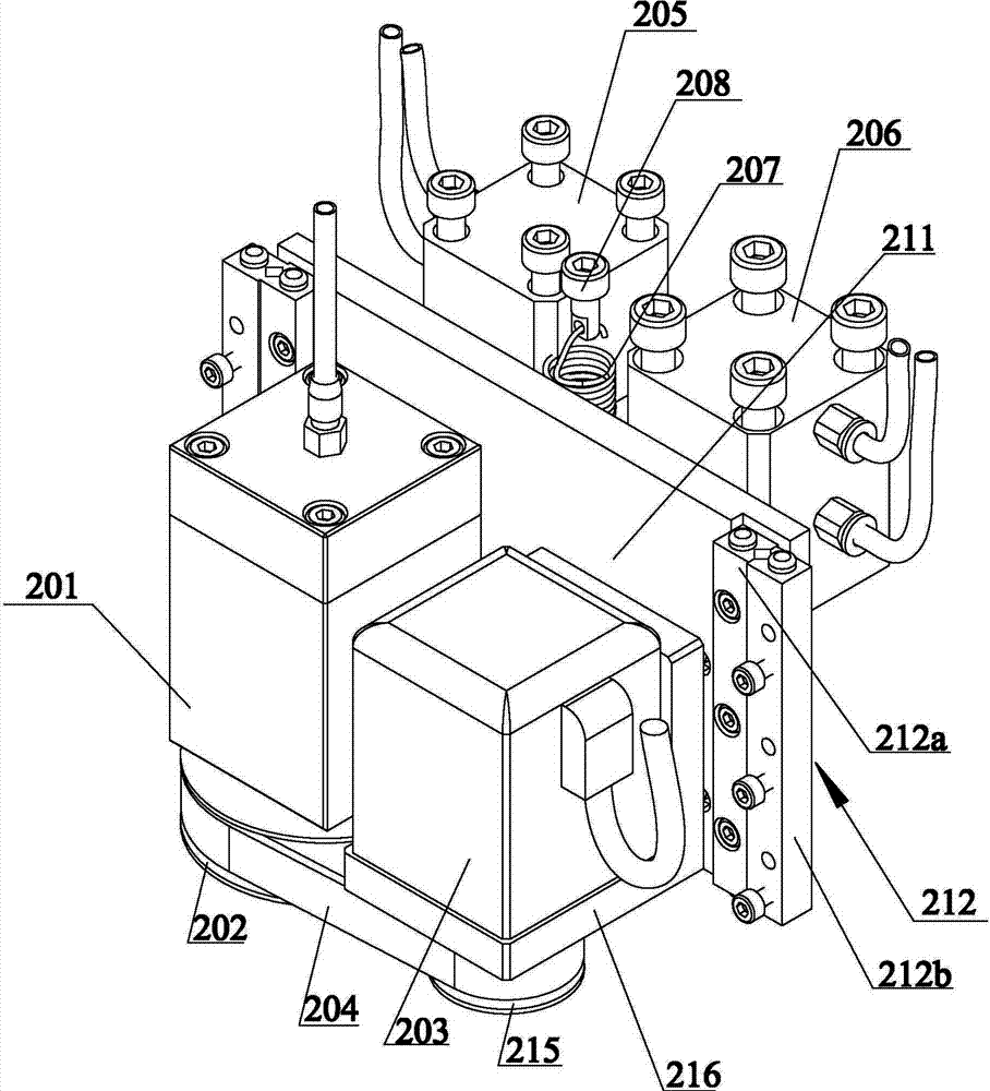
[0022] The pneumatic rotatable glass cutting machine includes a knife box lifting mechanism and a knife wheel rotating mechanism: the knife box lifting mechanism includes a knife box 201, a standard cylinder 205 for controlling the lifting of the knife box 201, and a low-friction cylinder 206. The lower end of the knife box 201 has a The cutter shaft 213 of the stepping rotary cutter wheel 214 is installed, the synchronous belt driven wheel 202 is fixed on the cutter shaft 213, the cutter box 201 is fixed on the front of the mounting plate 211, and the left and right sides of the mounting plate 211 respectively have a cross roller guide rail 212, cross The slide block 212a of the roller guide rail 212 is fixed on the mounting plate 211, the linear guide rail 212b of the cross roller guide rail 212 is fixed on ...


PUM


Abstract

The invention discloses a pneumatic rotatable glass cutting machine, which comprises a knife box lifting mechanism and a knife wheel rotating mechanism, wherein the knife box lifting mechanism consists of a first cylinder and a second cylinder, the first cylinder is fixedly arranged at the top of a cutting machine shell, a first cylinder check block is arranged right below the first cylinder and fixedly arranged on a mounting plate, the first cylinder check block is connected with the lower end of a lifting knife extension spring, and the upper end of the lifting knife extension spring is fixedly arranged at the top of the cutting machine shell; the second cylinder is fixedly arranged on the cutting machine shell, and a second cylinder check block is arranged right below the second cylinder and fixedly arranged on the mounting plate; and the knife wheel rotating mechanism comprises a motor, a synchronous belt driving wheel is arranged on a motor shaft and is connected with a synchronous belt driven wheel through a synchronous belt. The cutting machine adopts two-level knife falling, is accurate for a knife to fall so as not to easily crush glass, and wide in the range of application; after the cutting is completed, the knife is fast lifted by adopting the pull of the knife lifting extension spring, and the working efficiency can be improved; and the knife wheel is controlled to rotate by the motor, and the whole system is simpler.

Description

technical field [0001] The invention relates to the technical field of glass cutting, in particular to a pneumatic rotatable glass cutting machine for cutting special-shaped glass. Background technique [0002] Glass cutting machine is a processing machine dedicated to glass processing and blanking. In the prior art, glass cutting machines are mainly divided into semi-automatic cutting machines and full-automatic cutting machines. The semi-automatic cutting machines have a double-bridge overpass cutting table and a manual cutting table arranged end to end. The unit has the advantage of low cost. The machine can cut out various shapes of glass. [0003] The structure of the existing rotatable glass cutting machine is as follows: figure 1 As shown, it includes a knife rest 101, a cutter shaft 102 for installing a cutter wheel, a first motor 103 for controlling the lifting of the knife rest 101 and a second motor 104 for controlling the rotation of the knife shaft 102; the fi...

Claims


Application Information

Patent Timeline
Patent Type & Authority Applications(China)
IPC IPC(8): C03B33/027
Inventor 史国罕
Owner 史国罕
Why Eureka
Try Eureka