Automatic injection device

A technology of equipment and injection needles, which is applied in the directions of automatic injectors, syringes, hypodermic injection devices, etc., to achieve the effect of simple use

Active Publication Date: 2014-03-26
BECTON DICKINSON FRANCE
View PDF3 Cites 13 Cited by
  • Summary
  • Abstract
  • Description
  • Claims
  • Application Information

AI Technical Summary

Problems solved by technology

[0006] Additionally, many autoinjectors of the prior art are designed such that the container, such as the syringe, is assembled into th

Method used


Image

  • Automatic injection device
  • Automatic injection device
  • Automatic injection device

Examples


Embodiment Construction

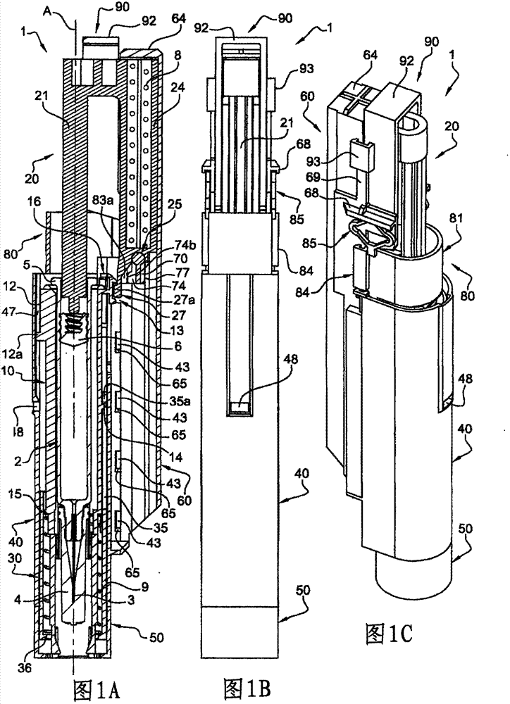
[0105] refer to Figures 1A-1C , shows a device 1 of the invention comprising:

[0106] - a syringe 2 comprising an injection needle 3 and a rubber cap 4 for protecting the injection needle, a flange 5, a stopper 6 and filled with the product 7,

[0107] - Syringe holder 10,

[0108] - plunger rod 20,

[0109] - needle protection sleeve 30,

[0110] - housing 40,

[0111] - protective cover 50,

[0112] - support 60,

[0113] - bar 70,

[0114] - locking member 80,

[0115] - button 90,

[0116] - first helical spring 8,

[0117] - Second helical spring 9 .

[0118] Referring to Figures 2-17B, the different parts of Figure 1 will now be described in detail.

[0119] refer to Figures 2A-2C , The syringe holder 10 has an overall tubular shape. It is shaped and dimensioned to be able to receive a syringe 2 with its flange 5 bearing on the proximal rim 11 of the syringe holder 10 . The syringe holder 10 is provided on its outer wall with a ridge 12 extending from the...


PUM


Abstract

The present invention relates to an automatic injection device (1) comprising : a container (2) having a longitudinal axis A and movable between a first position and a second position, in which the needle is inserted, biasing means (8), for moving the container to its second position, retaining means (70, 74, 74b) for maintaining said biasing means in a first stressed state, triggering means (90, 91 e) for releasing said retaining means, said retaining means comprising a lever member having a rotatable cylinder part and a radial projection extending therefrom, said radial projection being in a first angular position when said retaining means is in its passive condition, said radial projection being in a second angular position, different from said first angular position, when said retaining means is in its active condition, said rotatable cylinder part being included in a transversal plane of said longitudinal axis A.

Description

technical field [0001] The present invention relates to a device for injecting a product, the needle insertion step being automatic and performed with minimal effort by the user. Background technique [0002] In this application, the distal end of an element or device refers to the end furthest from the user's hand when said element or device is in the use position, and the proximal end refers to the end closest to the user's hand. Similarly, in this application, the terms "in the distal direction" and "distal" refer to the direction of injection, and the terms "in the proximal direction" or "proximal" refer to the direction opposite to the direction of injection . [0003] Devices for the automatic injection of products, also known as autoinjectors, are widely used in the medical field where daily injections are required, such as some treatments for diabetes, and in medical fields where patients often need to perform these injections themselves. Since the patient is not a...

Claims


Application Information

Patent Timeline
IPC IPC(8): A61M5/20A61M5/31A61M5/50
CPCA61M2205/582A61M5/3204A61M2005/3104A61M5/2033A61M5/326A61M2005/3143A61M2005/3142A61M2205/583A61M2005/206A61M5/5086A61M2205/581
Inventor F·卡雷尔L·马丽坦F·佩罗
Owner BECTON DICKINSON FRANCE
Why Eureka
Try Eureka