torque transfer device

A torque transmission device and torque technology, applied in the direction of electromechanical devices, magnetic circuit rotating parts, electrical components, etc., can solve the problems of high cost, high cost of rotor bracket, high cost of torque transmission device, etc., and achieve simple connection Effect

Inactive Publication Date: 2018-05-15
SCHAEFFLER TECH AG & CO KG
View PDF5 Cites 0 Cited by
  • Summary
  • Abstract
  • Description
  • Claims
  • Application Information

AI Technical Summary

Problems solved by technology

[0005] According to the prior art, the manufacture of the rotor carrier is cost-prohibitive, which in turn makes the overall construction of the torque transmission device cost-prohibitive and complex

Method used


Image

  • torque transfer device
  • torque transfer device
  • torque transfer device

Examples


Embodiment Construction

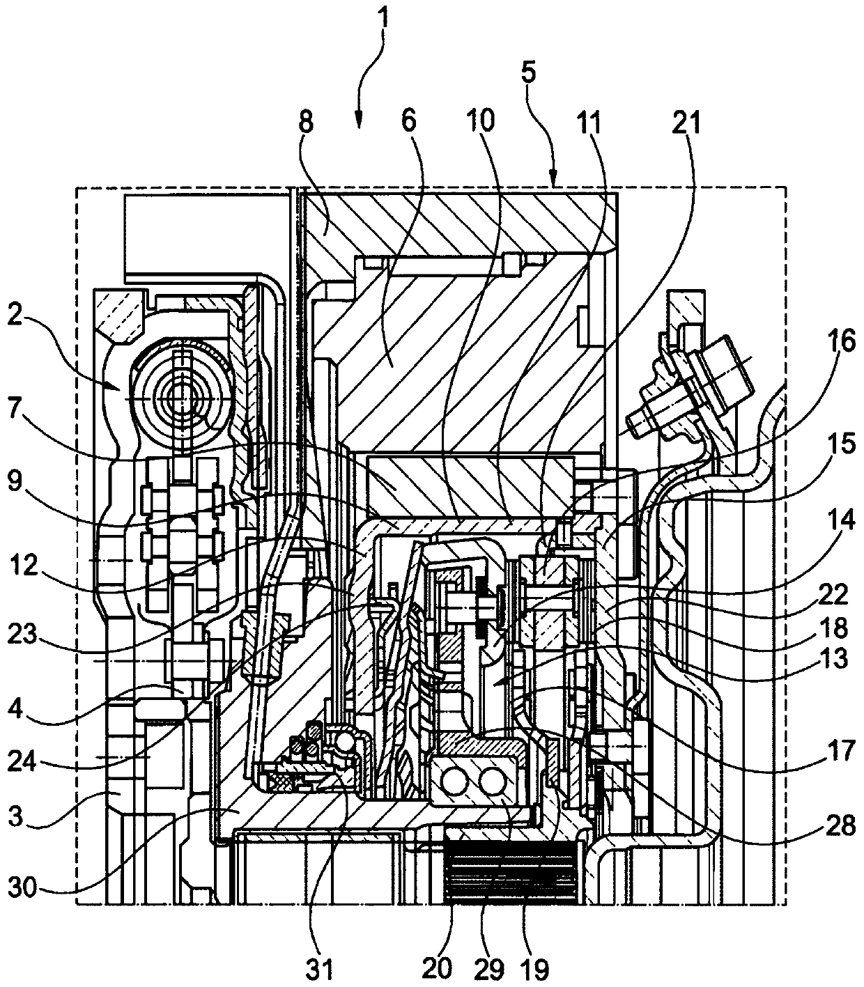
[0024] figure 1 A torque transmission device 1 is shown schematically with an input-side damping device 2 , wherein an input element 3 of the damping device 2 can be connected to an output element of an internal combustion engine. The output element 4 of the damping device 2 is preferably connectable to the transmission input shaft. The torque transmission device 1 also has an electric machine 5 , which is formed by a stator 6 and a rotor 7 . The stator 6 is carried here by a stator carrier 8 . In this case, the stator carrier 8 surrounds the stator 6 radially on the outside and fixes the stator 6 via the stator carrier 8 , for example in a sleeve of the torque transmission device 1 .

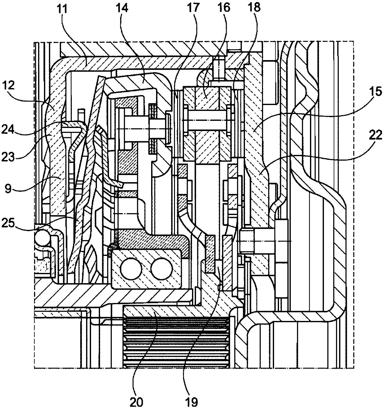
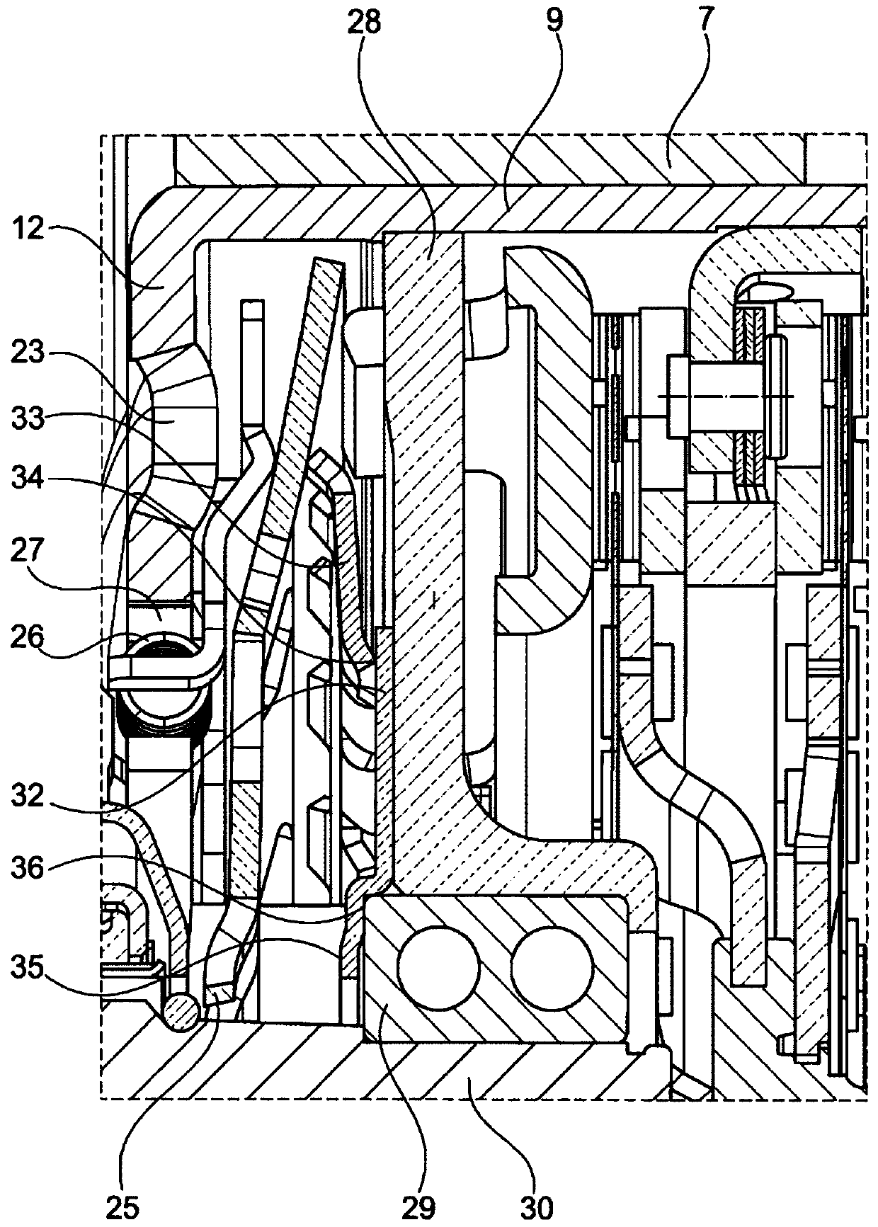
[0025] The rotor 7 is carried radially on the inside by a rotor carrier 9 . The rotor carrier 9 is designed here as a pot-shaped element 10 which has a first wall region 11 and a second wall region 12 . The first wall region 11 extends in the axial direction, wherein the second wall region ...


PUM


Abstract

The device (1) has an electric machine (5) with a stator (6) and a rotor (7). The rotor is arranged radially inside stator, and has a clutch (13) with a pressure plate (14) and a counter-pressure plate (15) and a clutch disc (19) that is arranged between pressure plate and counter-pressure plate and inside an output hub (20). The rotor is supported radially on inside by a rotor carrier (9) that is provided as cup-shaped element. The cup-shaped element has a wall portion (11) that extends in axial direction and a wall portion (12) that extends in radial direction.

Description

technical field [0001] The invention relates to a torque transmission device, in particular for a drive train of a motor vehicle with an internal combustion engine and an electric machine. Background technique [0002] Torque transmission devices are known in the prior art with a very simple design. Torque transmission devices are used in particular in the drive train of a motor vehicle with an internal combustion engine and an electric machine for transmitting drive-side torque via the output side to the transmission. [0003] A torque transmission device in the drive train of a motor vehicle with an internal combustion engine and an electric machine is thus known, for example, from DE 199 37 545 A1. [0004] DE 10 2010 054 545 A1 also discloses such a torque transmission device for a drive train of a motor vehicle with an internal combustion engine and an electric machine. In this case, the electric machine is formed by a stator and a rotor, wherein the rotor is rotatabl...

Claims


Application Information

Patent Timeline
Patent Type & Authority Patents(China)
IPC IPC(8): H02K7/108H02K1/22H02K7/10F16D13/60
CPCF16D25/087F16D25/126H02K7/108
Inventor W·鲁德S·马科维亚克
Owner SCHAEFFLER TECH AG & CO KG
Why Eureka
Try Eureka