Manufacturing method of antenna device

A technology of antenna device and manufacturing method, applied in the directions of antenna support/mounting device, antenna coupling, radiation element structure form, etc., can solve the problems such as bad influence of antenna device 935 characteristics, large-scale, antenna device 935 exceeding, etc., and achieve solution Adverse effects, the effect of solving large-scale

Inactive Publication Date: 2014-04-02
ALPS ALPINE CO LTD
View PDF6 Cites 1 Cited by
  • Summary
  • Abstract
  • Description
  • Claims
  • Application Information

AI Technical Summary

Problems solved by technology

Therefore, the mounting terminal 927 functions as a part of the antenna radiating element 923, which has a problem of adversely affecting the characteristics of the antenna device 935.
[0008] Furthermore, in order to avoid the generation of this parasitic capacitance, it is conceivable to separate the mounting terminal 927 from the antenna radiation element 923. However, if this method is adopted, the antenna device 935 will be larger than necessary.

Method used


Image

  • Manufacturing method of antenna device
  • Manufacturing method of antenna device
  • Manufacturing method of antenna device

Examples


Embodiment Construction

[0053] Embodiments of the present invention will be described below with reference to the drawings.

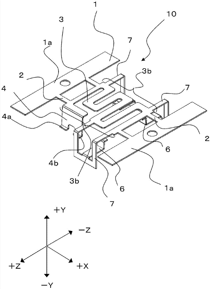
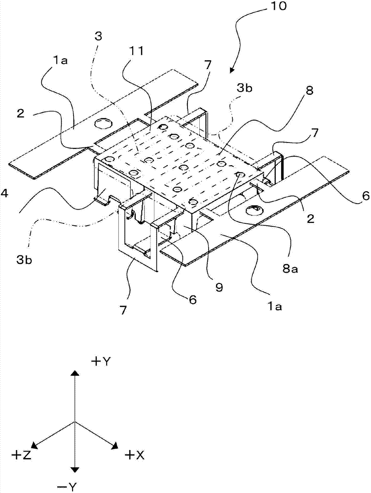
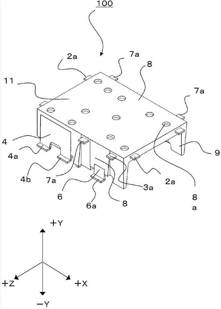
[0054] The present invention is an antenna device manufacturing method for manufacturing an antenna device based on an antenna component made of metal, figure 1 It is a perspective view after bending the antenna component involved in the antenna device manufacturing method of the present invention. figure 2 for right figure 1 The perspective view of the antenna part after resin inlay molding, image 3 for right figure 2 A perspective view of the antenna assembly after cutting and removing the link stack.

[0055] In the antenna device manufacturing method related to the embodiment of the present invention, after punching the metal plate 1 according to the shape of the antenna, as figure 1 As shown, the stamped metal sheet 1 is bent, whereby the antenna component 10 is formed. In addition, the detail of a bending process is mentioned later.

[0056] Such as figure ...


PUM


Abstract

The present invention provides a manufacturing method of an enchasing moulding antenna device which can not change large and the character of which can not suffer ill effects brought by mounting terminals. The manufacturing method of the antenna device includes: an antenna component (10) bended by the bending process is conducted an enchasing moulding process and a severing process to cut the first linkage stack (2) and the second linkage (7), bending the second linkage (7) outside the end face (3b) of a radiant element of the antenna device at the bending process and bending the mounting terminals (6) in order to make the front end (6c) of the mounting terminals (6) to be installed inside of the end face (3b) of the radiant element of the antenna device, a resin (8) turning into a leg (9) to support the main body of the antenna device (100) and the resin (8) provided with the mounting terminals (6).

Description

technical field [0001] The present invention relates to a method of manufacturing an antenna device, and more particularly to a method of manufacturing an antenna device molded with resin. Background technique [0002] Conventionally, as an antenna device used for a wireless LAN (Local Area Network) or a GPS (Global Positioning System) in a portable device, a camera, etc., an antenna device formed based on an antenna radiating element composed of a single metal plate has been used. Among such antenna devices, an antenna device has been proposed that has a plurality of mounting terminals for supporting the antenna radiating element and integrates the antenna radiating element and the plurality of mounting terminals with resin. [0003] For example, if Figure 7 The antenna device 935 of Patent Document 1 shown in (a) and (b) includes an antenna radiating element 923 and a plurality of mounting elements 927 that support the antenna radiating element 923 . A feed terminal 929 ...

Claims


Application Information

Patent Timeline
Patent Type & Authority Applications(China)
IPC IPC(8): H01Q1/52H01Q1/12H01Q1/36
Inventor 东俊之松崎聪千田悟
Owner ALPS ALPINE CO LTD
Why Eureka
Try Eureka