Cleaning apparatus
An instrument and cleaning technology, applied in the field of cleaning instruments, can solve the problems of time-consuming, unsatisfactory cleaning process results, etc.
- Summary
- Abstract
- Description
- Claims
- Application Information
AI Technical Summary
Problems solved by technology
Method used
Image

Examples
Embodiment Construction
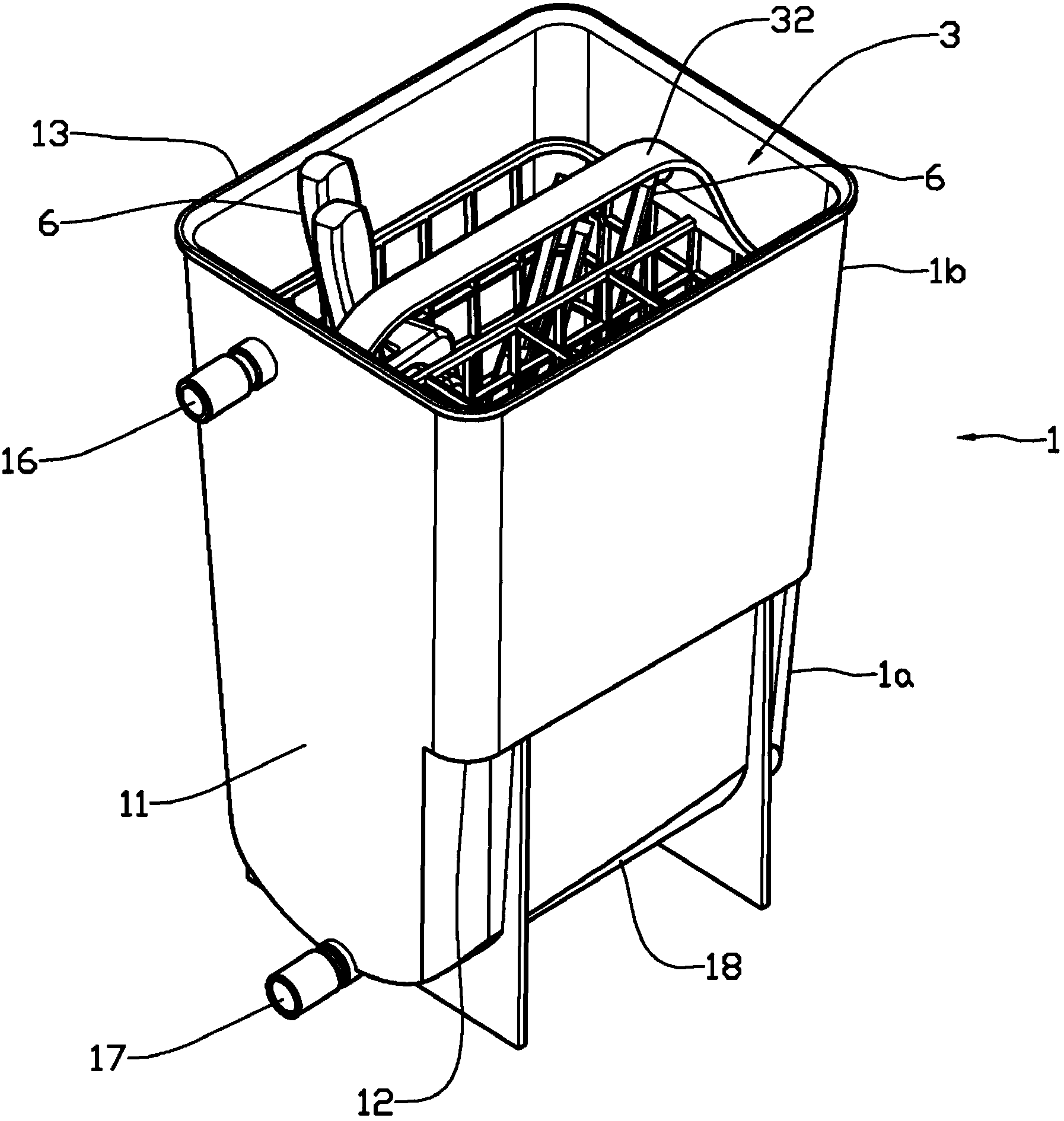
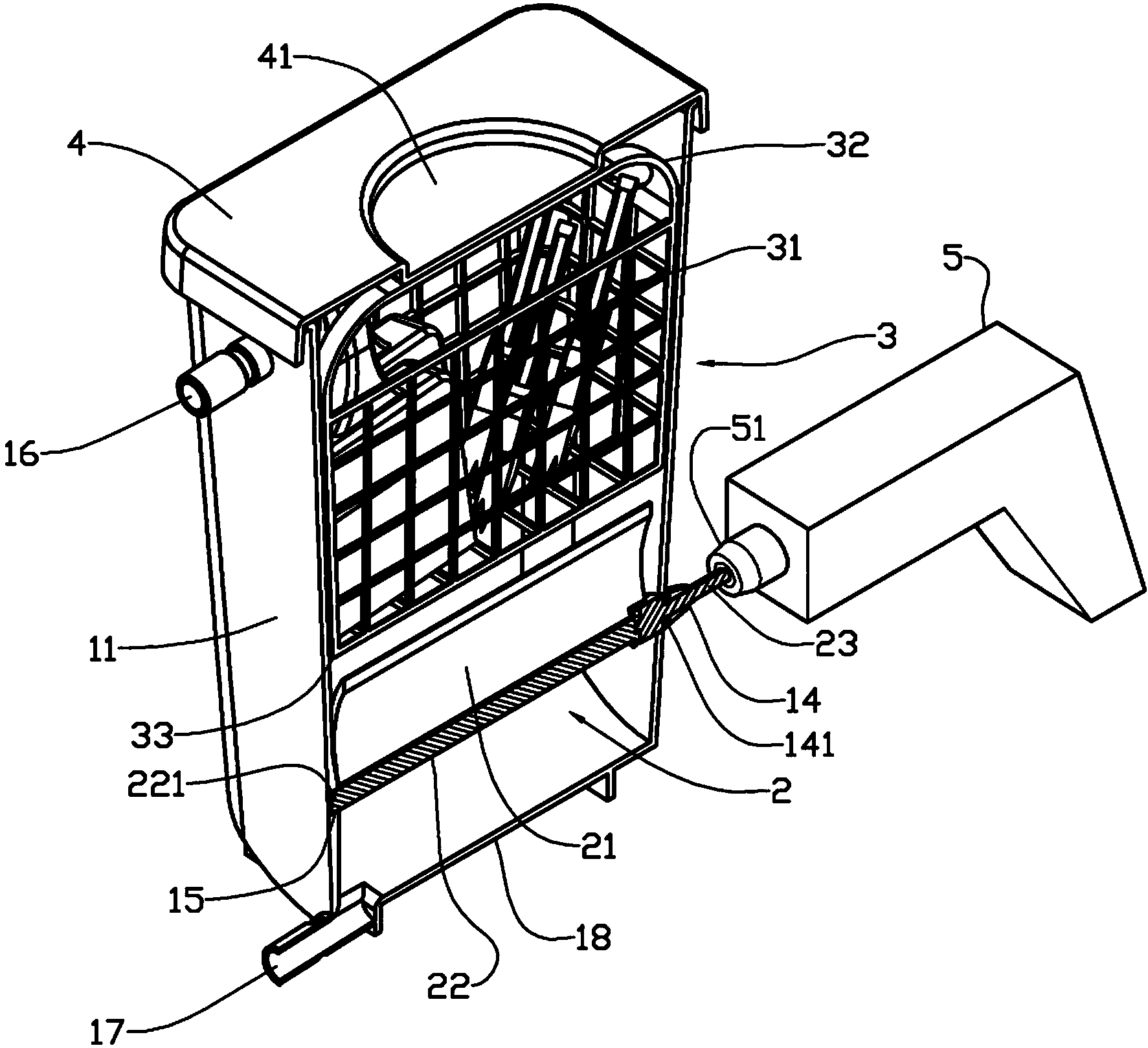
[0023] In the figures, reference numeral 1 is a container having an open top 13 arranged to be closed with a lid 4 . In the lower part la, the container contains the paddle wheel 2 . The upper part 1b of the container 1 is arranged to include means for securing items to be cleaned, here shown as a removable threaded basket 3 designed to keep brushes and other painting equipment standing upright. A drive device 5 , here schematically shown as an electric drill (drill bit) with a tool connector 51 (supporter), is connected to the drive shaft 23 protruding from the container 1 .
[0024] The paddle wheel 2 is arranged with a horizontal central shaft supported in recesses 15 of two opposing vessel side walls 11 . The bottom 18 of the container is arranged corresponding to the groove of the paddle wheel 2 , whereby the bottom 18 shows a defined clearance relative to the paddle wheel 2 . The tip of the paddle wheel 2 is kept at a prescribed distance from the side wall 11 . A driv...
PUM
 Abstract
Description
Claims
Application Information
 - R&D
- Intellectual Property
- Life Sciences
- Materials
- Tech Scout
- Unparalleled Data Quality
- Higher Quality Content
- 60% Fewer Hallucinations
Browse by: Latest US Patents, China's latest patents, Technical Efficacy Thesaurus, Application Domain, Technology Topic, Popular Technical Reports.
© 2025 PatSnap. All rights reserved.Legal|Privacy policy|Modern Slavery Act Transparency Statement|Sitemap|About US| Contact US: help@patsnap.com