Exhaust purification device of internal combustion engine

一种排气净化装置、内燃机的技术,应用在排气装置、排气处理装置的电控、内燃活塞发动机等方向,能够解决车辆搭载性恶化、制造成本增大等问题

Active Publication Date: 2014-04-16
TOYOTA JIDOSHA KK
View PDF10 Cites 1 Cited by
  • Summary
  • Abstract
  • Description
  • Claims
  • Application Information

AI Technical Summary

Problems solved by technology

[0013] However, according to the technology disclosed in the above-mentioned Patent Document 1, since a plurality of reducing agent supply devices are arranged, there is a technical problem that the manufacturing cost may increase and the vehicle mountability may deteriorate.

Method used


Image

  • Exhaust purification device of internal combustion engine
  • Exhaust purification device of internal combustion engine
  • Exhaust purification device of internal combustion engine

Examples


Embodiment Construction

[0052] Hereinafter, embodiments of the present invention will be described with reference to the drawings.

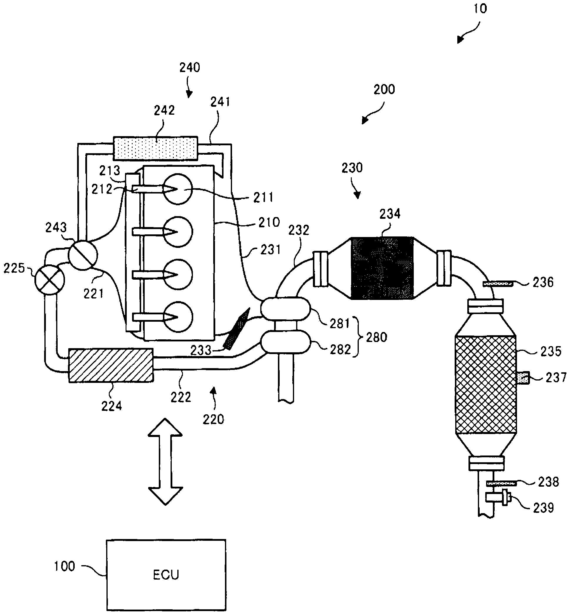
[0053] First, refer to figure 1 The configuration of an engine system including an exhaust purification device for an internal combustion engine according to an embodiment of the present invention will be described.

[0054] figure 1 It is a schematic configuration diagram schematically showing the configuration of the engine system of the present embodiment.

[0055] exist figure 1 Here, the engine system 10 is mounted on a vehicle not shown, and has an ECU (Engine Control Unit: Engine Control Unit) 100 and an engine 200 .

[0056] The ECU 100 is an electronic control unit including a CPU (Central Processing Unit), a ROM (Read Only Memory), a RAM (Random Access Memory), and the like, and controls all operations of the engine 200 . ECU 100 is configured to be able to execute various controls according to a control program stored in, for example, a ROM. In addition,...


PUM


Abstract

An exhaust purification device of an internal combustion engine comprises: a first catalyst (234) provided to an exhaust channel of an internal combustion engine (200); a second catalyst (235) provided to the exhaust channel on the downstream side of the first catalyst; a reducing agent supply means (233) provided to the upstream side of the first catalyst and used for supplying a reducing agent in the exhaust channel; and a reducing agent supply control means (100) for controlling the reducing agent supply means so that the air-fuel ratio on the upstream side of the first catalyst instantaneously becomes rich.

Description

technical field [0001] The invention relates to the technical field of exhaust purification devices for internal combustion engines. Background technique [0002] As a technique for purifying the exhaust gas of internal combustion engines such as diesel engines, for example, there is known a technique in which HC (hydrocarbons) and CO (oxygen monoxide) in the exhaust gas are oxidized (that is, burned) in the exhaust passage of the internal combustion engine. The oxidation catalyst (DOC: Diesel Oxidant Catalyst: Diesel Oxidation Catalyst), which captures the carbon-based particulate matter (PM: Particulate Matter: Particulate Matter) in the exhaust gas is called DPF (Diesel Particulate Filter: Diesel Particulate Matter). filter) filter catalyst, etc. (for example, refer to Patent Document 1 to Patent Document 3). [0003] When the amount of particulate matter (hereinafter appropriately referred to as “PM”) captured by the filter catalyst increases, the exhaust pressure may i...

Claims


Application Information

Patent Timeline
Patent Type & Authority Applications(China)
IPC IPC(8): F01N3/02
CPCF01N3/2892F01N13/009Y02T10/24F01N3/208F01N3/035F01N3/20Y02T10/47F01N3/206F01N9/00F01N3/0253F01N2900/1602F01N3/0821F01N3/0864F01N3/103F01N9/002F01N2560/025F01N2900/1621F01N2900/1622Y02T10/40
Inventor 森俊博美才治悠树
Owner TOYOTA JIDOSHA KK
Why Eureka
Try Eureka