Supercharge Your Innovation With Domain-Expert AI Agents!

Quantitative spray valve

A spray valve and quantitative valve technology, which is applied in fixed measuring chambers, lifting valves, valve devices, etc., can solve the problems of cumbersome air and liquid filling methods and the inability to achieve quantitative spraying, etc.

Active Publication Date: 2016-01-27
徐礼才
View PDF7 Cites 0 Cited by
  • Summary
  • Abstract
  • Description
  • Claims
  • Application Information

AI Technical Summary

Problems solved by technology

[0003] The deficiency of above-mentioned prior art is: can not realize quantitative spraying;

Method used


Image

  • Quantitative spray valve
  • Quantitative spray valve
  • Quantitative spray valve

Examples


Embodiment 1

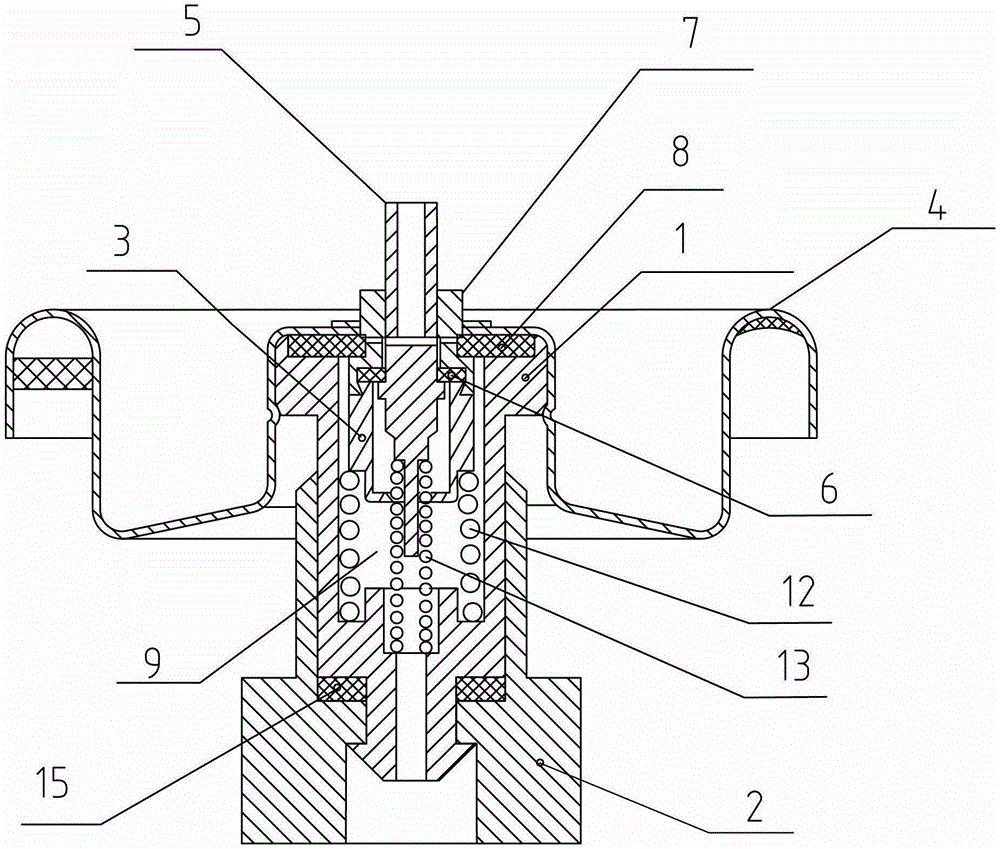
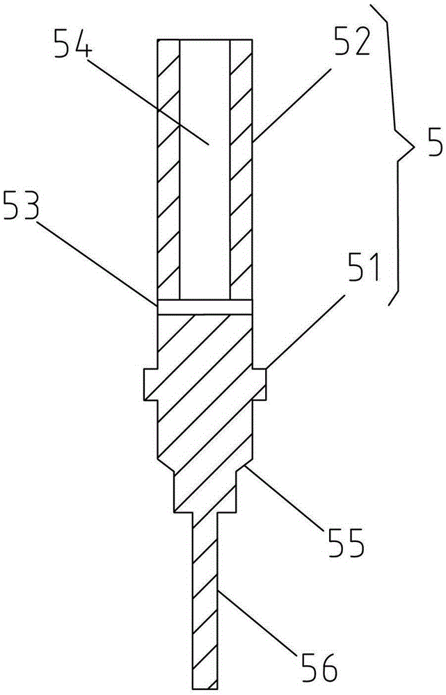
[0028] Such as figure 1 , the quantitative spray valve of this embodiment includes: an inner valve body 1, a quantitative valve chamber 3 arranged in the inner valve body 1, a sealing cover 4 sealingly fitted on the top of the quantitative valve chamber 3, and an axially penetrating sealing cover. 4 and the inner valve stem 5 of the quantitative valve chamber 3; the middle part of the inner valve stem 5 is provided with an annular boss 51, and a first sealing ring 6 is arranged between the quantitative valve chamber 3 and the sealing cover 4, and the first sealing ring 6 Seal fit with the upper rod body 52 above the annular boss 51 of the inner valve rod 5; the upper rod body 52 is provided with radially distributed liquid inlet holes 53 and axially distributed liquid discharge holes 54; The bottom of the liquid hole 54 communicates with the liquid inlet 53; the lower rod body of the inner valve rod 5 below the annular boss 51 is provided with a first annular cone surface 55, ...

Embodiment 2

[0035] On the basis of Embodiment 1, the quantitative spray valve of this embodiment has the following deformations:

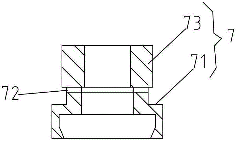
[0036] See Figures 1 to 7 , in order to achieve the purpose of filling the soft bag through the inner valve stem, the quantitative spray valve provided in this embodiment also includes: an outer valve stem 7; the bottom of the outer valve stem 7 passes through the first sealing ring 6 and the The top of the quantitative valve chamber 3 is sealed and fit, the middle part of the outer valve stem 7 has an annular platform 71, and the second sealing ring 8 is passed between the rod body 73 above the annular platform 71 and the sealing cover 4 of the outer valve stem 7 sealing fit; the rod body 73 of the outer valve stem 7 above the annular platform 71 is provided with a radial through hole 72, and the two ends of the radial through hole 72 are in sealing fit with the inner ring of the second sealing ring 8 A first spring 12 is provided between the bottom of the ...

Embodiment 3

[0040] On the basis of Embodiment 2, the quantitative spray valve of this embodiment has the following deformations:

[0041] See Figures 9 to 10 , the inner wall of the lower end of the outer valve body 2 is provided with a sleeve 21, the lower end of the inner valve body 2 is a tubular part 1-2 with a diameter smaller than that of the inner valve body 2, and the tubular part 1-2 extends into the sleeve 21, the sleeve 21 is also covered with a snap ring 14 that makes the contact surface of the tubular part 1-2 and the sleeve 21 airtight, so that the contact surface of the inner valve body 2 and the outer valve body 2 airtight between. In order to improve the anti-leakage effect, a third sealing ring 15 is provided between the outer valve body 2 and the inner valve body 1 .


PUM


Abstract

The present invention relates to a metered dose aerosol valve, comprising: an internal valve body, a dose-metering valve chamber arranged inside the internal valve body, and an internal valve stem axially penetrating the dose-metering valve chamber; a middle part of the internal valve stem is provided with an annular boss, a first gasket is fixedly arranged on the dose-metering valve chamber, and the first gasket matches an upper stem body, located above the annular boss, of the internal valve stem in a sealing manner; the upper stem body is provided with radially distributed liquid inlet holes and axially distributed liquid discharge holes; a bottom of the liquid discharge hole is in communication with the liquid inlet hole; a lower stem body, located below the annular boss, of the internal valve stem is provided with a first annular conical face, an end opening at a bottom of the dose-metering valve chamber is provided with a second annular conical face, and the first and second annular conical faces are vertically opposite to each other; and when the internal valve stem is pressed down, and the internal valve stem is moved down until the liquid inlet hole on the internal valve stem is located below the first gasket, the first and second annular conical faces are adapted to match each other in a sealing manner, so it is possible to only spray out liquid inside the dose-metering valve chamber, thereby implementing a metered dose aerosol spraying function.

Description

technical field [0001] The invention relates to a quantitative spray valve. Background technique [0002] Chinese patent ZL200810020952.4 relates to a spray valve with good airtightness and internal leakage prevention. The valve body includes: an inner valve body made of impermeable materials such as POM and an outer valve body made of weldable materials such as PE, and the outer valve body is sealed and sleeved on the outside of the inner valve body. When in use, the outer valve body is sealed and connected with the inlet of the soft bag. Since the outer valve body is made of PE material, it is convenient to make a sealed connection with the soft bag, but the PE material is permeable to gas, while the inner valve body is made of POM material. It has good strength and good air tightness, so its anti-permeation performance is better, so these two materials are made into the inner and outer valve body of the valve body respectively, which not only meets the needs of the valve...

Claims


Application Information

Patent Timeline
Patent Type & Authority Patents(China)
IPC IPC(8): G01F11/28B65D83/44B65D83/60F16K1/00B65D83/14
CPCB65D83/54B65D83/425B65D83/62
Inventor 徐礼才
Owner 徐礼才
Features
  • R&D
  • Intellectual Property
  • Life Sciences
  • Materials
  • Tech Scout
  • Unparalleled Data Quality
  • Higher Quality Content
  • 60% Fewer Hallucinations
Learn More