Thrust rudder linking rod mechanism of flap type rudder

The technology of a link mechanism and a flap rudder is applied in the improvement field of the flap rudder pushing rudder link mechanism, and can solve the problems such as damage to the flap rudder and increase of the resistance of the rudder to the rudder.

Inactive Publication Date: 2014-05-28
JIANGSU HUAYANG HEAVY IND +1
View PDF8 Cites 0 Cited by
  • Summary
  • Abstract
  • Description
  • Claims
  • Application Information

AI Technical Summary

Problems solved by technology

[0002] Flap rudders are more and more used on ships because of their good rudder turning effect and simple structure. The rotation of the wing rudder in the current flap rudder is driven by the rudder linkage mechanism. The existing flap rudder push rudder linkage The rod mechanism is mainly composed of the rudder stock cover and the rudder connecting rod. One end of the rudder connecting rod is rotatably connected to the hull. The other end of the rod is rotatably connected together by a bearing. The rudder thrust linkage mechanism of this structure can effectively push the wing rudder to rotate, but the disadvantage is that when the flap rudder is installed or working, the rudder stock cover and the thrust rudder When the axes of the connecting rods do not coincide, it will increase the rudder turning resistance of the wing rudder, and even cause damage to the flap rudder. At present, there is no flap rudder that can overcome the above shortcomings, and it has not been reported in the data and media found in

Method used


Image

  • Thrust rudder linking rod mechanism of flap type rudder

Examples


Embodiment Construction

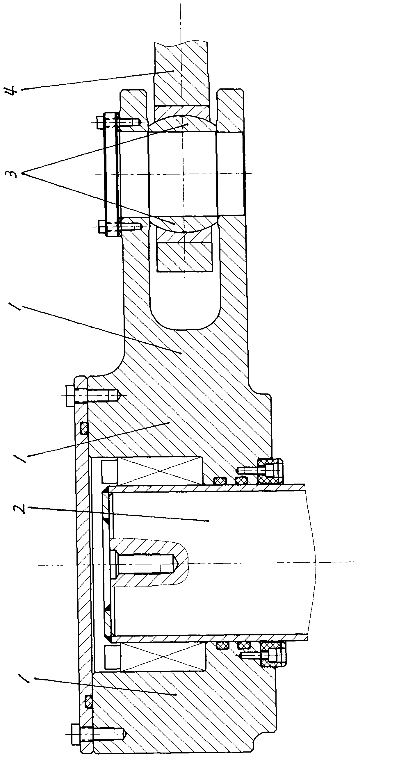
[0008] figure 1 Among them, the flap rudder pusher link mechanism is mainly composed of wing rudder stock 2, rudder stock cover 1 and rudder link 4, and one end of the rudder link 4 is rotatably connected to the hull (not shown in the hull figure). ), one end of the rudder stock cover 1 is affixed to the top of the wing rudder stock 2, the other end of the rudder stock cover 1 and the other end of the rudder connecting rod 4 are rotatably connected together by a bearing 3, and the bearing 3 is a spherical bearing. When the axes of the rudder stock cover 1 and the rudder connecting rod 4 at the joint do not coincide, the rudder stock cover 1 and the rudder connecting rod 4 will not seize each other at the joint due to the good deflection performance of the spherical bearing , so the rudder turning resistance of the wing rudder will not be increased, thereby improving the reliability of the flap rudder and prolonging the service life of the flap rudder.


PUM


Abstract

The invention relates to ship equipment, in particular to an advanced thrust rudder linking rod mechanism of a flap type rudder. The thrust rudder linking rod mechanism comprises a wing rudder rod, a rudder rod sleeve and a thrust rudder linking rod, wherein one end of the thrust rudder linking rod is rotatably connected onto a ship body, one end of the rudder rod sleeve is fixedly connected onto the top of the wing rudder rod, and the other end of the rudder rod sleeve and the other end of the thrust rudder linking rod are rotatably connected via a spherical bearing. When axes of the rudder rod sleeve and the thrust rudder linking rod are not coincident at the joint, rudder shifting resistance for the wing rudder cannot be enlarged, reliability of the flap type rudder is improved, and service life of the flap type rudder is prolonged.

Description

Technical field: [0001] The invention relates to ship equipment, in particular to the improvement of a flap rudder pusher linkage mechanism. Background technique: [0002] Flap rudders are more and more used on ships because of their good rudder turning effect and simple structure. The rotation of the wing rudder in the current flap rudder is driven by the rudder linkage mechanism. The existing flap rudder push rudder linkage The rod mechanism is mainly composed of the rudder stock cover and the rudder connecting rod. One end of the rudder connecting rod is rotatably connected to the hull. The other end of the rod is rotatably connected together by a bearing. The rudder thrust linkage mechanism of this structure can effectively push the wing rudder to rotate, but the disadvantage is that when the flap rudder is installed or working, the rudder stock cover and the thrust rudder When the axes of the connecting rods do not coincide, it will increase the rudder turning resistan...

Claims


Application Information

Patent Timeline
IPC IPC(8): B63H25/10
Inventor 丁晓阳陈宁丁郁华何志忠徐志明朱洁刘小琴王进储慧琳金雪磊马从龙王玲
Owner JIANGSU HUAYANG HEAVY IND
Why Eureka
Try Eureka