Eccentric compression column non-unloading strengthening testing device
A technology of eccentric compression column and test device, which is applied in the direction of applying stable tension/pressure to test the strength of materials, etc., which can solve problems that do not conform to the actual situation of the project, poor voltage stabilization effect, large machine loss, etc., and save scientific research funds The effect of time and time, easy operation and simple structure
Inactive Publication Date: 2014-05-28
HUNAN UNIV OF TECH
View PDF3 Cites 3 Cited by
- Summary
- Abstract
- Description
- Claims
- Application Information
AI Technical Summary
Problems solved by technology
[0005] The purpose of the present invention is to overcome the problems in the prior art of poor pressure stabilization effect, large machine loss, inconvenient use and failure of the entire test due to local concrete crushing at the end of the column before the specimen reaches the ultimate bearing capacity, and to provide a Non-unloading reinforcement test device for eccentric compression columns. This device is not only simple in structure, safe and reliable, but also has a good pressure stabilization effect under high loads, ensuring that the loaded column end will not be damaged before the specimen reaches the ultimate bearing capacity.
[0006] Through a large number of domestic a
Method used
View moreImage
Smart ImageViewing Examples
Examples
 PUM
 Abstract
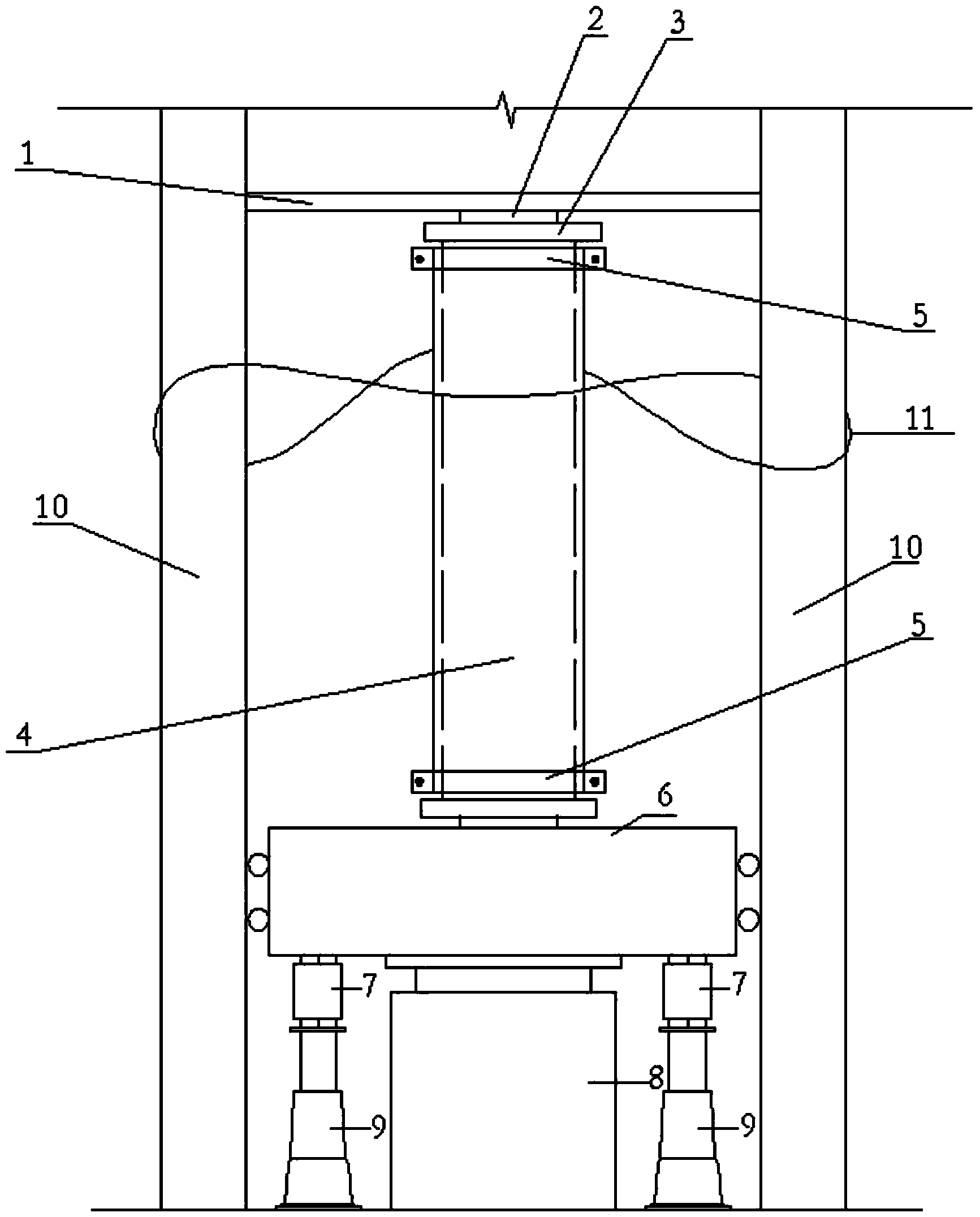
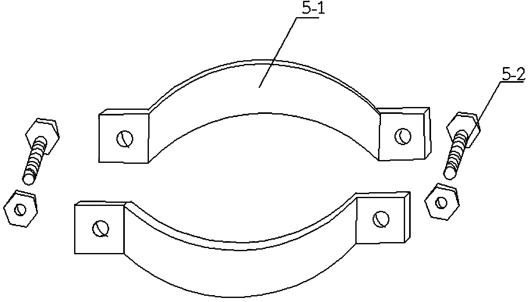
The invention discloses an eccentric compression column non-unloading strengthening testing device. The testing device comprises a counter-force stiff frame, a movable stiff beam capable of moving up and down, a loading exerting device, two force sensors and two deformeters connected with the two force sensors, wherein the counter-force stiff frame consists of two stiff frame stand columns and a fixed beam; a testing column to be tested is mounted between the fixed beam and the movable stiff beam; the movable stiff beam is arranged between the two stiff frame stand columns; both a one-way knife hinge and a pressure distribution plate are arranged between the testing column and the fixed beam arranged at the upper end of the testing column and between the testing column and the movable stiff beam arranged at the lower end of the testing column; each pressure distribution plate is in contact with the end face at the end of the testing column; the testing device further comprises tightening pieces arranged in pairs and mounted at the ends of the testing column; each tightening piece consists of two semicircular steel plates and bolts. According to the invention, the testing device is good in controllability, simple in structure and convenient to operate; that partial concrete at the end of the testing column is crushed before the whole test-pieces are damaged can be avoided, otherwise, the test is enabled to fail.
Description
technical field [0001] The invention belongs to a test device, in particular to a non-unloading reinforcement test device for an eccentric compression column. Background technique [0002] If the compression member that is being put into use needs to be reinforced, it should be unloaded first so that the effect of the reinforcement layer can be fully exerted, but it is difficult to do this in actual engineering, and it can only be partially unloaded or not unloaded at all, that is, The original component has been subjected to load before reinforcement, which is called the first-stage load. After reinforcement, only when the external load continues to increase, which is called the second-stage load, and the deformation of the component continues to increase, the reinforcement layer will Assist the original member to bear the new external load, which makes the stress and strain of the original member ahead of the reinforcement layer. [0003] At present, the test of non-unloa...
Claims
Login to View More Application Information
Patent Timeline
 IPC IPC(8): G01N3/12
Inventor 蒋隆敏施棉军
Owner HUNAN UNIV OF TECH
Features
- R&D
- Intellectual Property
- Life Sciences
- Materials
- Tech Scout
- Unparalleled Data Quality
- Higher Quality Content
- 60% Fewer Hallucinations
Learn More Browse by: Latest US Patents, China's latest patents, Technical Efficacy Thesaurus, Application Domain, Technology Topic, Popular Technical Reports.
© 2025 PatSnap. All rights reserved.Legal|Privacy policy|Modern Slavery Act Transparency Statement|Sitemap|About US| Contact US: help@patsnap.com


