Improvements in gasification and/or pyrolysis

A technology of pyrolysis and hot gas, which is applied in the field of gasification and pyrolysis of waste), which can solve the problems of clogging and reducing the effectiveness of stirring devices.

Inactive Publication Date: 2014-06-25
CHINOOK END STAGE RECYCLING
View PDF7 Cites 0 Cited by
  • Summary
  • Abstract
  • Description
  • Claims
  • Application Information

AI Technical Summary

Problems solved by technology

This not only reduces the effectiveness of known stirring devices, but also clogs the mechanical type of stirrer provided in the oven

Method used


Image

  • Improvements in gasification and/or pyrolysis
  • Improvements in gasification and/or pyrolysis
  • Improvements in gasification and/or pyrolysis

Examples


Embodiment Construction

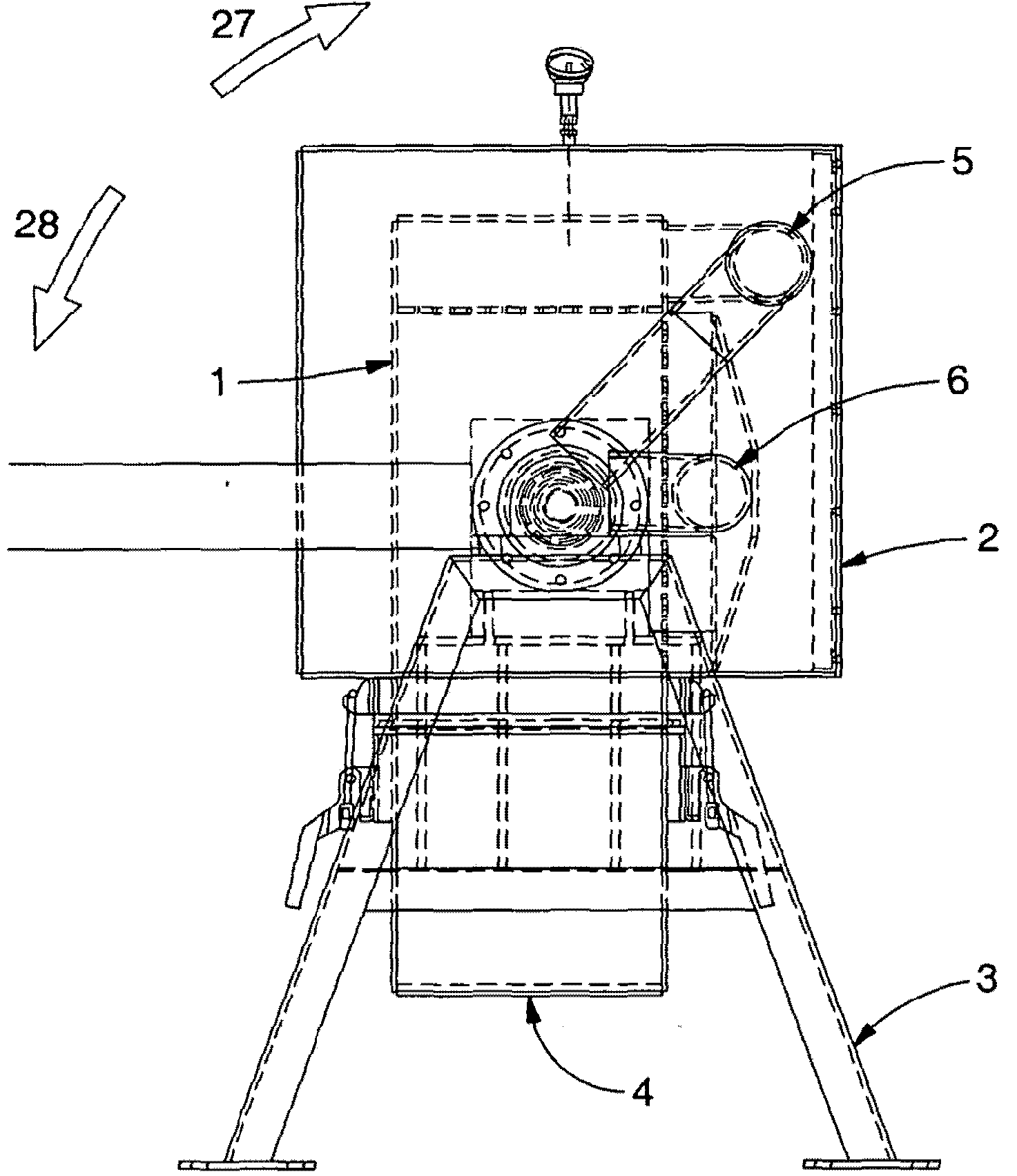
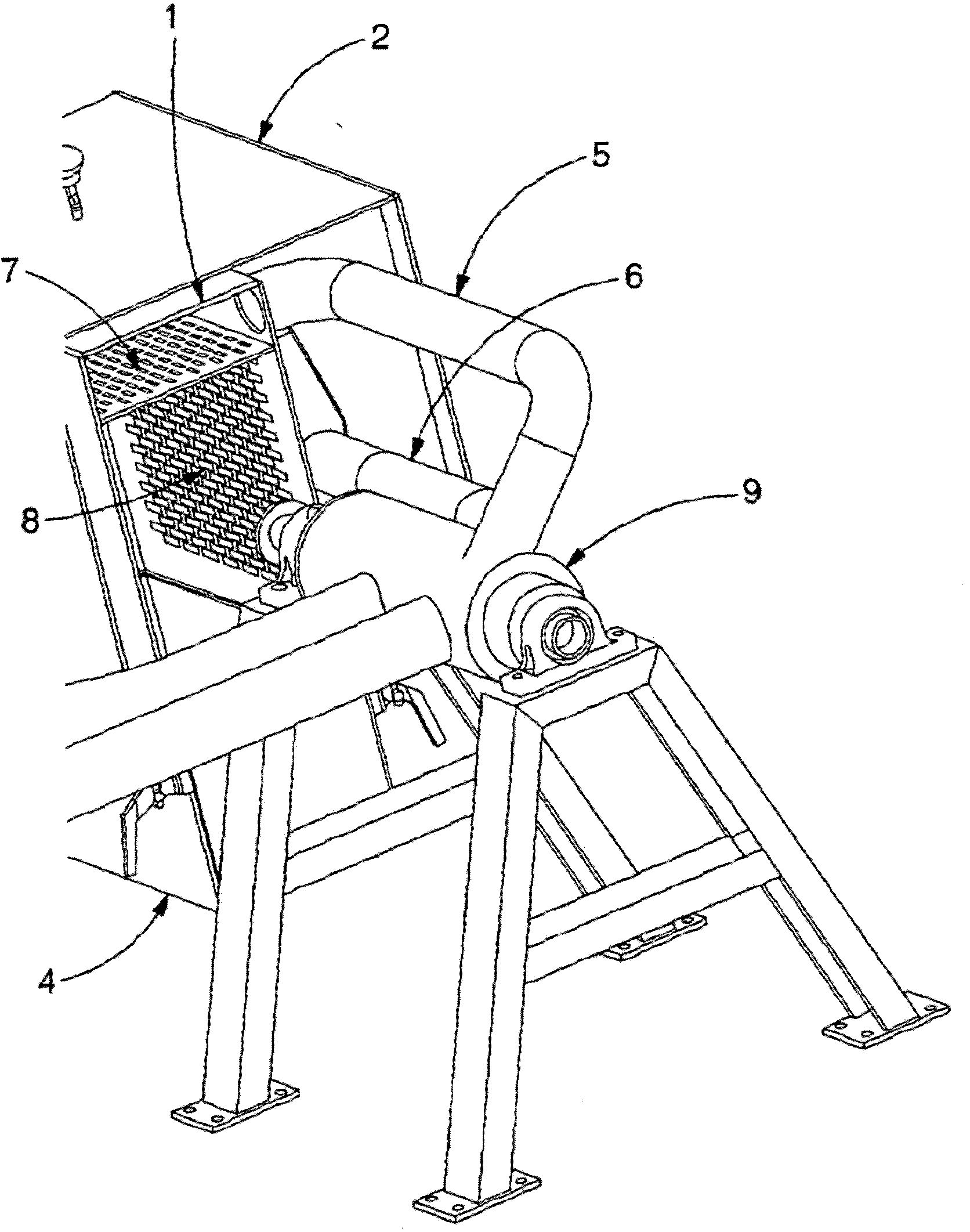
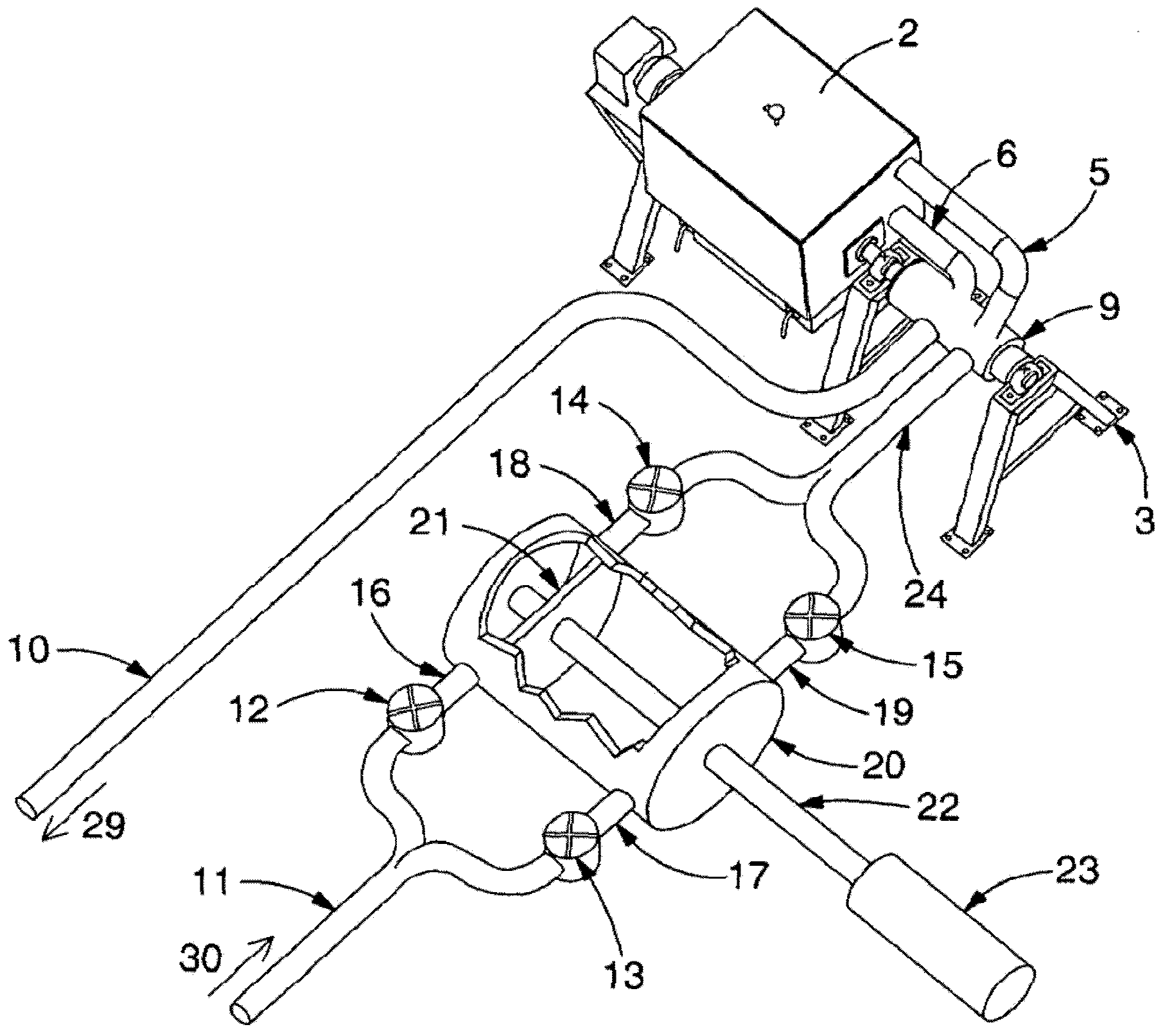
[0023] As mentioned above, the invention can be used in gasification / pyrolysis chambers described in prior art documents as static or as rotating. The embodiments specifically described herein relate to a rotating version of the chamber, although it will be apparent to those skilled in the art how the invention can be modified for use with a static version of the oven. The protection scope of the present invention is not limited to the above two forms (static form and rotating form).

[0024] figure 1 with figure 2 Shown is a gasification / pyrolysis machine having a housing 2 in which a process chamber 1 is mounted to contain and process material. The material may be waste material comprising organic components, such as municipal waste or industrial waste, or alternatively any material comprising organic matter. The waste is loaded into a removable container 4 which is then connected to the device.

[0025] The hot air enters the processing chamber 1 through the intake pip...


PUM


Abstract

The present invention provides a method and apparatus for gasifying / pyrolysing material containing organic matter including introducing the material into a treatment chamber (2) and heating the material by passing a flow of hot gas (30) containing less than 8% oxygen through the chamber (2) so as to cause the material therein to gasify or pyrolyse. In a first mode of operation the gas (30) is passed through the chamber (2) at a first velocity. The apparatus comprises a means (20, 21) for temporarily increasing the velocity of the hot gas (30) such that in a second mode of operation the velocity of the gas (30) exiting the means (20, 21) is temporarily increased.

Description

technical field [0001] The present invention relates to the gasification and pyrolysis of materials, such as wastes containing organic components, and in particular, the present invention relates to improving the efficiency of methods and apparatus for performing gasification and pyrolysis. Background technique [0002] Pyrolysis and gasification of organic materials in static and rotating process chambers is common knowledge in the art. Static processing chambers and rotating processing chambers are generally classified as batch processing devices, which process one batch of material at a time, and constant (continuous) processing devices, which have a constant through-flow of material. Heating of the material is typically accomplished by passing hot gases through the processing chamber. In order to maintain constant process parameters, the gas flow is usually adjusted to maintain a relatively constant flow rate, and the flow rate of hot gas can often be determined accordi...

Claims


Application Information

Patent Timeline
Patent Type & Authority Applications(China)
IPC IPC(8): F04B35/01F04B37/18
CPCF04B35/01C10J2200/09F23G5/0276C10J3/002F04B37/18C10J3/30F23G5/50C10J3/00F23G5/44
Inventor 约翰·特纳
Owner CHINOOK END STAGE RECYCLING
Why Eureka
Try Eureka