A device for fatigue testing of fork

A fatigue test and fork technology, which is applied in the design field of helicopter fork fatigue test device, can solve the problems of lack of fork fatigue test device and inability to test, etc.

Active Publication Date: 2016-12-28
CHINA HELICOPTER RES & DEV INST
View PDF4 Cites 0 Cited by
  • Summary
  • Abstract
  • Description
  • Claims
  • Application Information

AI Technical Summary

Problems solved by technology

[0003] At present, there is no fork fatigue test device in our country, so this kind of test cannot be carried out
No relevant foreign literature was retrieved

Method used


Image

  • A device for fatigue testing of fork

Examples


Embodiment Construction

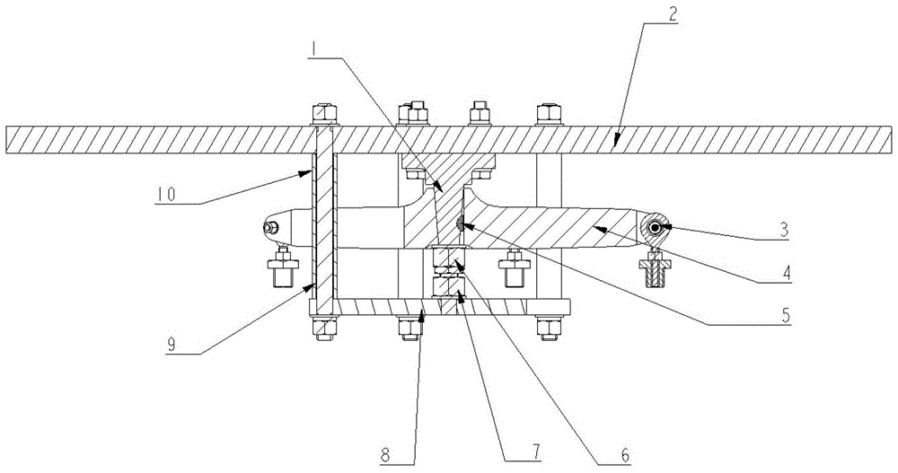
[0008] The present invention will be described in further detail below.

[0009] Such as figure 1 As shown, the present invention is a fork-shaped member fatigue test device, comprising: a simulated shaft 1, a top plate 2, a joint bearing assembly 3, a fork-shaped member 4, a key 5, an adjusting nut 6, a limit nut 7, a lower bottom plate 8, The bolt 9 and the support sleeve 10 are composed of the fork 4 inserted into the simulation shaft 1, which has threads on the simulation shaft 1, the position of the fork 4 on the simulation shaft 1 is adjusted by the adjustment nut 6, and the center of the lower bottom plate 8 has a hole, which simulates The end of the shaft 1 is inserted into the hole, and the installation position of the lower bottom plate 8 is adjusted through the limit nut 7. There are holes around the lower bottom plate 8, which are connected with the top plate 2 through bolts 9 and support sleeves 10, and tightened with mounting nuts. Joint bearings Assembly 3 is c...


PUM


Abstract

The invention designs a Y-piece fatigue test device. According to the invention, stress state during installation of a Y-piece is simulated completely, and load can simultaneously be applied on each support arm of the Y-piece, so as to achieve the purpose of examining fatigue performance of the Y-piece. The technical scheme of the invention is as follows: the device is composed of a simulation shaft, a top board, a joint bearing assembly, the Y-piece, a key, an adjusting nut, a spacing nut, a lower plate and a support sleeve; the Y-piece is inserted in the simulation shaft which is threaded; the position of the Y-piece on the simulation shaft is adjusted through the adjusting nut; the center of the lower plate is provided with a hole and an end portion of the simulation shaft is inserted in the hole; installation position of the lower plate is adjusted through the spacing nut; the periphery of the lower plate is provided with holes; the lower plate is connected with the top board through bolts and the support sleeve, and the bolts are tightened with installation nuts; the joint bearing assembly is connected with the Y-piece through bolts; and the joint bearing assembly is connected with the Y-piece to test load.

Description

technical field [0001] The invention belongs to the fatigue test technology of a helicopter fork, and relates to the design of a fatigue test device for a helicopter fork. Background technique [0002] The fork is an important control part of the tail rotor, and each arm of the fork needs to bear the load at the same time. In order to grasp the fatigue performance of the fork, it is necessary to conduct a fatigue test on the fork on the ground, to grasp the fatigue characteristics of the fork, and then to give the life of the fork. [0003] At present, there is no fork fatigue test device in our country, so this kind of test cannot be carried out. No relevant foreign publications were retrieved. Contents of the invention [0004] The technical problem to be solved by the present invention is to design a fork-shaped fatigue test device, which can completely simulate the stress state of the fork when it is installed, and can apply loads to each arm of the fork at the same ...

Claims


Application Information

Patent Timeline
Patent Type & Authority Patents(China)
IPC IPC(8): G01M13/00
Inventor 夏国旺吴希明张植群
Owner CHINA HELICOPTER RES & DEV INST
Why Eureka
Try Eureka