
A torque loading device for the joint of the main rocker arm

A technology of torque loading and shaft loading, which is applied in the design field of torque loading test device for the joint of the main lifter arm of the helicopter, and can solve the problems that there is no fatigue test device for the joint of the main lifter arm, and the test cannot be performed.

Active Publication Date: 2017-12-29
CHINA HELICOPTER RES & DEV INST
View PDF8 Cites 0 Cited by
  • Summary
  • Abstract
  • Description
  • Claims
  • Application Information

AI Technical Summary

Problems solved by technology

[0003] At present, there is no fatigue test device for the main lifter arm joint in my country, so this kind of test cannot be carried out
No relevant foreign literature was retrieved

Method used


Image

  • A torque loading device for the joint of the main rocker arm
  • A torque loading device for the joint of the main rocker arm
  • A torque loading device for the joint of the main rocker arm

Examples


Embodiment 1

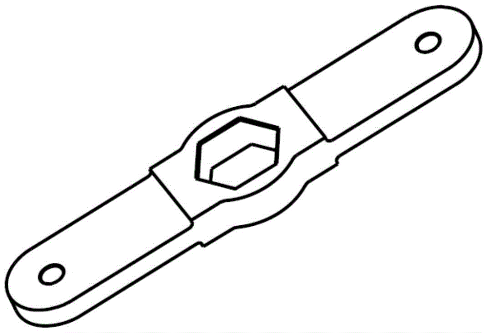
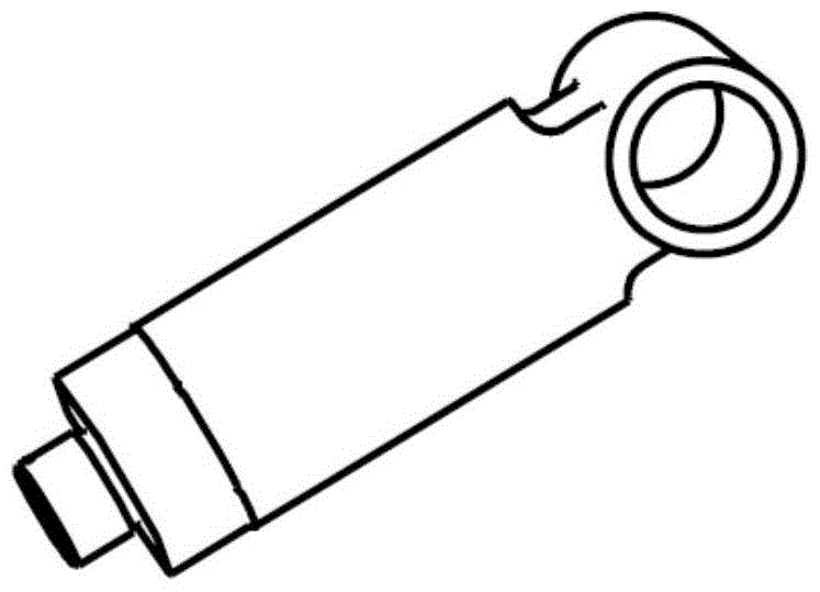
[0023] A torque loading device for a main rocker arm joint, characterized in that it includes a loading joint 1, a torque arm 3, a torque balance bar 6, a loading shaft 7, a rocker dummy 8 and a joint bearing assembly 9; the torque balance bar 6 One end is connected with the rocker dummy 8, and the other end is connected with the joint bearing assembly 9. The rocker dummy 8 has a T-shaped structure as a whole, and a shaft hole is opened at the front end, and one end of the loading shaft 7 extends into the shaft hole. 8 is fastened to the center of the torsion arm 3, the rear end of the rocker dummy 8 is connected to one end of the torque balance bar 6, the other end of the torque balance bar 6 is connected to the joint bearing assembly 9, and the rocker dummy 8 is connected to the On the main rocker arm joint, the axis of the inner hole of the joint bearing assembly 9 is on the rotation axis of the rocker arm dummy 8 .

[0024] One end of the torque balance rod 6 is threaded, ...

Embodiment 2

[0033] see below Figure 5 This patent is described in further detail. The torque loading device for the joint of the main lifting rocker arm consists of a loading joint 1, a connecting bolt 2, a torque arm 3, a large locking nut 4, a tightening nut 5, a torque balance rod 6, a loading shaft 7, a dummy rocker arm 8, and a joint bearing Component 9, base 10, characterized in that the rocker dummy 8 is connected to the main rocker joint 11 through the loading shaft 7, the torque arm 3 is installed on the rocker dummy 8 and fixed on the rocker by locking the big nut 4 On the arm dummy 8 , one end of the torque balance rod 6 is threadedly connected to the rocker dummy 8 . The other end is connected to the joint bearing assembly 9, and the joint bearing assembly 9 is screwed to the base 10. The loading joint 1 is connected to the torque arm 3, and the test load is applied through the connected actuator. Before the test, adjust the height by turning the joint bearing assembly 9 s...


PUM


Abstract

A torque loading device for a main rocker arm joint, belonging to the fatigue test technology of a helicopter main rocker arm joint, characterized in that it includes a loading joint, a torque arm, a torque balance bar, a loading shaft, a rocker dummy and a joint bearing; One end of the torque balance rod is connected to the dummy rocker arm, and the other end is connected to the joint bearing assembly. The dummy rocker arm is a T-shaped structure as a whole, with a shaft hole at the front end, and one end of the loading shaft extends into the shaft hole. The dummy rocker arm is tight. The center of the torsion arm is fixedly connected, the rear end of the dummy rocker arm is connected to one end of the torque balance bar, the other end of the torque balance bar is connected to the joint bearing, the dummy rocker arm is connected to the joint of the main rocker arm through the loading shaft, and the inside of the joint bearing The axis of the hole is on the axis of rotation of the rocker dummy. The invention has the advantages of simulating the stressed state of the joint of the main rocker arm, loading torque without limiting the degree of freedom of the joint of the main lifter arm, and achieving the purpose of assessing the fatigue performance of the joint of the main lifter arm.

Description

technical field [0001] The invention belongs to the fatigue test technology of the joint of the main lift arm of a helicopter, and relates to the design of a torque loading test device for the joint of the main lift arm of a helicopter. Background technique [0002] The main rocker arm joint is an important part of the main landing gear, and at the same time bears the torque load of the landing gear rocker arm and the tensile pressure and shear force of the frame beam on it. In order to grasp the fatigue performance of the main rocker arm joint, it is necessary to conduct fatigue tests on the main rocker arm joint on the ground, to grasp the fatigue characteristics of the main rocker arm joint, and then to give the life of the main rocker arm joint. [0003] At present, there is no fatigue test device for the joint of the main crank arm in my country, so this kind of test cannot be carried out. No relevant foreign publications were retrieved. Contents of the invention ...

Claims


Application Information

Patent Timeline
Patent Type & Authority Patents(China)
IPC IPC(8): G01M13/00
Inventor 孙云伟张澄彬李清蓉
Owner CHINA HELICOPTER RES & DEV INST
Learn More