

Self-luminous display device, control method of self-luminous display device, and computer program
A display device and self-illumination technology, which is applied to static indicators, instruments, etc., can solve problems such as deterioration of luminous characteristics and brightness reduction, and achieve the effect of suppressing image persistence
Active Publication Date: 2014-07-02
JOLED INC
View PDF7 Cites 1 Cited by
- Summary
- Abstract
- Description
- Claims
- Application Information
AI Technical Summary
Problems solved by technology
[0006] However, in an organic EL element, when a voltage is continuously applied, the luminous characteristics will deteriorate, and even if the same current is input, the luminance will decrease
Method used
View moreImage
Smart ImageViewing Examples

Examples
Embodiment approach
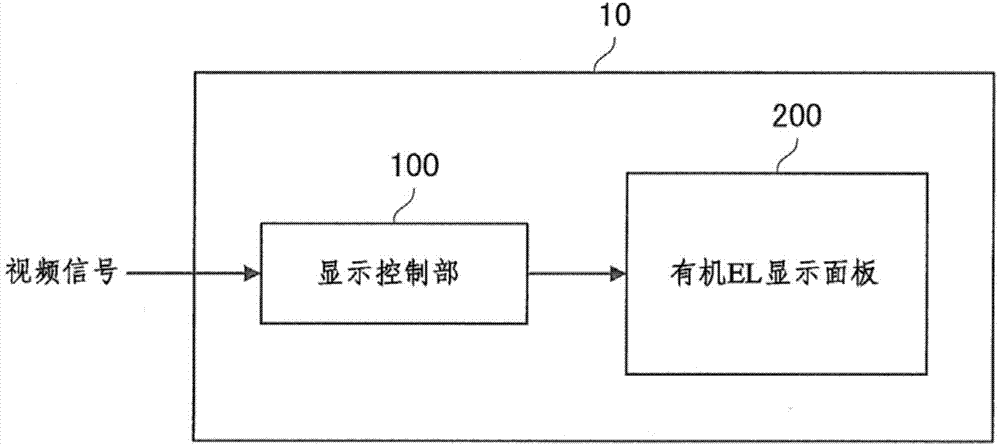
[0045] [Configuration example of self-luminous display device]
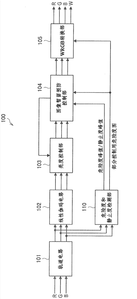
[0046] [Configuration example of display control unit]
[0047] [Example of configuration of risk level and static level detection unit]
[0048] [Example of brightness control and image persistence prevention control]
[0049] [Example of WRGB conversion processing using risk map for portion control]
[0050] 2. Conclusion
[0051] 1. Embodiments of the present invention
Login to View More PUM
 Abstract
Provided is a self-luminous display device including a data calculation section configured to calculate, by using a supplied video signal, data relating to a luminance amount accumulated in a unit of a first block in a target region for luminance control in a screen on which a plurality of pixels are arranged in a matrix, each of the pixels including a light emitting element which emits light by itself according to a current amount, a resampling section configured to resample the data relating to the luminance amount in the target region, in a unit of a second block, the data relating to the luminance amount being calculated by the data calculation section, the second block being larger than the first block, and a scaling section configured to generate data for luminance control in the target region by scaling the data resampled by the resampling section. According to the invention, the luminance can be calculated according to the video signal, and the image persistence phenomenon of the screen can be inhibited flexibly by controlling the video signals.
Description
technical field [0001] The present invention relates to a self-luminous display device, a control method and a computer program for the self-luminous display device. Background technique [0002] As flat-panel thin display devices, liquid crystal display devices using liquid crystals and plasma display devices using plasma have been put into practical use. [0003] A liquid crystal display device is a display device provided with a backlight, which displays an image by changing the arrangement of liquid crystal molecules by applying a voltage and by transmitting and shielding light from the backlight. In addition, a plasma display device is a display device that has a plasma state by applying a voltage to a gas enclosed in a substrate, and passes ultraviolet rays (ultraviolet rays are generated by energy generated when returning from a plasma state to an initial state) Images are displayed by irradiating phosphors to convert ultraviolet rays into visible light. [0004] On...
Claims
Login to View More Application Information
Patent Timeline
 Patent Type & Authority Applications(China)
IPC IPC(8): G09G3/32
CPCG09G2330/04G09G2320/046G09G2320/029G09G2320/0285G09G2340/06G09G3/3208G09G3/2003G09G3/3406G09G2360/16
Inventor 井上泰夫船津阳平清水荣寿内田高史
Owner JOLED INC