Cable synchronizer system

A technology of actuation system and flexible cable, applied in the direction of linear motion axis, shaft, flexible shaft, etc., can solve the problems of damage to surrounding parts and increase of stress of surrounding parts, etc.

Active Publication Date: 2014-07-09
LEGGETT & PLATT CANADA
View PDF5 Cites 11 Cited by
  • Summary
  • Abstract
  • Description
  • Claims
  • Application Information

AI Technical Summary

Problems solved by technology

This situation can result in a delay between releasing the first latch and releasing the second latch, which

Method used


Image

  • Cable synchronizer system
  • Cable synchronizer system
  • Cable synchronizer system

Examples


Embodiment Construction

[0014] Before any embodiment of the invention is explained in detail, it is to be understood that the invention is not limited in application to the details of construction and arrangement of parts set forth in the following description or illustrated in the drawings. The invention is capable of other embodiments and of being practiced or carried out in various ways. Also, it is to be understood that the phraseology and terminology used herein are for the purpose of description and should not be regarded as limiting. The use of "comprising", "including" or "having" and variations thereof herein means that what is listed thereafter and equivalents thereof as well as additional items are encompassed. Moreover, as used herein and in the appended claims, the terms "upper," "lower," "top," "bottom," "front," "rear," and other directional terms are not intended to No special orientation is required, but is for descriptive purposes only.

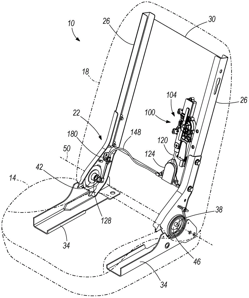
[0015] figure 1 Seat 10 is exemplified, a...


PUM


Abstract

An actuation system for concurrently actuating a first mechanism and a second mechanism from a first state to a second state includes an actuator and a sliding member operatively engaged with the actuator and movable from a first position to a second position in response to actuation of the actuator. A connecting member has a relaxed state and a taut state. The connecting member includes a first end coupled to the first mechanism, a second end coupled to the second mechanism, and a medial portion cooperative with the sliding member. Movement of the sliding member from the first position to the second position changes the connecting member from the relaxed state to the taut state, whereby the tension is increased in the connecting member.

Description

Background technique [0001] The present invention relates to a system for synchronously actuating multiple components, for example, synchronously actuating opposed vehicle seat latches to allow a vehicle seat folding operation. [0002] Foldable seating systems typically include a recliner mechanism with opposed latches on each side of the seat bottom that collectively hold the seat in an upright position. The folding action of the seat can be manually initiated or powered by pressing a button to release these latches. Often, separate cables run from the actuator mechanism to a lever or similar device coupled to each latch. Because these individual cables may have different tolerances or degrees of deflection, actuating the folding operation of the seat does not necessarily result in simultaneous release of the latches. This situation can result in a delay between releasing the first latch and releasing the second latch, which delay can lead to increased stress in and to one...

Claims


Application Information

Patent Timeline
IPC IPC(8): B60N2/30B60N2/90
CPCB60N2/2356F16C2326/08F16C1/106F16C1/12B60N2/929Y10T74/20402B60N2/20B60N2/02253B60N2/02246F16C1/10
Inventor 霍里亚·布兰迪尔罗伯特·J·麦克米伦保罗·廷德尔
Owner LEGGETT & PLATT CANADA
Why Eureka
Try Eureka