Radio frequency identification tester calibration device and method

A technology for radio frequency identification and calibration devices, which is applied in the direction of measuring devices, instruments, and measuring electrical variables, etc., and can solve problems such as calibration specifications or verification procedures for radio frequency identification (RFID) testers that have not been promulgated

Inactive Publication Date: 2014-07-16
SHANGHAI INST OF MEASUREMENT & TESTING TECH
View PDF4 Cites 9 Cited by
  • Summary
  • Abstract
  • Description
  • Claims
  • Application Information

AI Technical Summary

Problems solved by technology

So far, the country has not promulgated radio frequency identification (RFID) tester calibration specifications or verification procedures

Method used


Image

  • Radio frequency identification tester calibration device and method
  • Radio frequency identification tester calibration device and method
  • Radio frequency identification tester calibration device and method

Examples


Embodiment 1

[0035] The present invention provides a radio frequency identification tester calibration device, comprising:

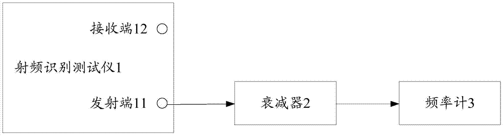
[0036] Such as figure 1 As shown, the attenuator connected to the transmitting end 11 of the radio frequency identification tester 1, the input end of the attenuator 2 is connected to the transmitting end 11, and the frequency meter 3 connected to the output end of the attenuator 2, the The frequency meter 3 is used to read the count value of the output frequency of the radio frequency identification tester 1 by the attenuator 2;

[0037] Such as figure 2 As shown, the microwave power meter 4 connected to the output end of the attenuator 2, the microwave power meter 4 is used to obtain the count value of the output power of the radio frequency identification tester 1 through the attenuator 2;

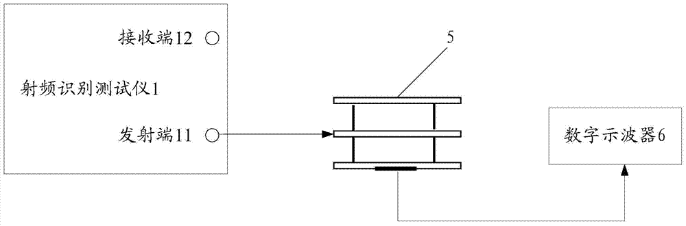
[0038] Such as image 3 As shown, the induction coil connected to the transmitting end 11 of the radio frequency identification tester 1, the input end of the induction coil...

Embodiment 2

[0043] Such as Figure 1~6 As shown, the present invention also provides another radio frequency identification tester calibration method, using the radio frequency identification tester calibration device of Embodiment 1, the method includes:

[0044] Step 1, after setting the output frequency and output power of the radio frequency identification tester, the radio frequency identification tester outputs a continuous, unmodulated signal to the frequency meter through the attenuator, and reads the count value of the output frequency from the frequency meter; specifically Yes, the instrument connection in this step is as follows figure 1 shown;

[0045] Step 2: After setting the output frequency and output power of the radio frequency identification tester, the radio frequency identification tester outputs a continuous, unmodulated signal to the microwave power meter through the attenuator, and reads the count value of the output power from the microwave power meter , determi...


PUM


Abstract

The invention provides a radio frequency identification tester calibration device and method. The device comprises an attenuator, a frequency meter, a microwave power meter, an induction coil, a vector signal analyzer and a signal generator, wherein the transmitting end of a radio frequency identification tester is connected with the attenuator, the frequency meter is connected with the output end of the attenuator, the microwave power meter is connected with the output end of the attenuator, the induction coil is connected with the transmitting end of the radio frequency identification tester, the output end of the induction coil is connected with a digital oscilloscope, the vector signal analyzer is connected with the transmitting end of the radio frequency identification tester, the signal generator is connected with receiving end of the radio frequency identification tester, and the output end of the signal generator is connected the receiving end of the radio frequency identification tester and the input end of the microwave power meter. The radio frequency identification tester calibration device and method can precisely calibrate the radio frequency identification tester used during radio frequency identification card testing.

Description

technical field [0001] The invention relates to a calibration device and method for a radio frequency identification tester. Background technique [0002] Radio Frequency Identification (RFID) testers are widely used in the R&D, production and testing of RFID cards. RFID testers include RFID transmitters and RFID receivers. The transmitters emit the required RFID signals, and the RFID cards receive the RFID signals. , After decoding, the signal is sent back, and the RF tester receives the signal sent back by the RFID card and demodulates it correctly. Therefore, whether the radio frequency identification tester is accurate and reliable will be very important for the testing of RFID cards. So far, the country has not promulgated radio frequency identification (RFID) tester calibration specifications or verification procedures. Contents of the invention [0003] The purpose of the present invention is to provide a radio frequency identification tester calibration device an...

Claims


Application Information

Patent Timeline
Patent Type & Authority Applications(China)
IPC IPC(8): G01R35/00
Inventor 詹志强陆福敏于磊夏铭来磊蔡青桑昱
Owner SHANGHAI INST OF MEASUREMENT & TESTING TECH
Why Eureka
Try Eureka