Intermittent spring expansion hinge reducing mechanism

A deceleration mechanism and intermittent technology, applied in the direction of pivot connection, etc., can solve the problem of high deployment speed and achieve the effect of avoiding excessive deployment speed

Active Publication Date: 2014-07-23
HARBIN INST OF TECH
View PDF5 Cites 15 Cited by
  • Summary
  • Abstract
  • Description
  • Claims
  • Application Information

AI Technical Summary

Problems solved by technology

[0003] The purpose of the present invention is to solve the problem that the existing solar wing deployment hinge driven by scroll springs is prone to locking impact due to excessive deployment speed, and to provide an intermittent spring deployment hinge deceleration mechanism

Method used


Image

  • Intermittent spring expansion hinge reducing mechanism
  • Intermittent spring expansion hinge reducing mechanism
  • Intermittent spring expansion hinge reducing mechanism

Examples


specific Embodiment approach 1

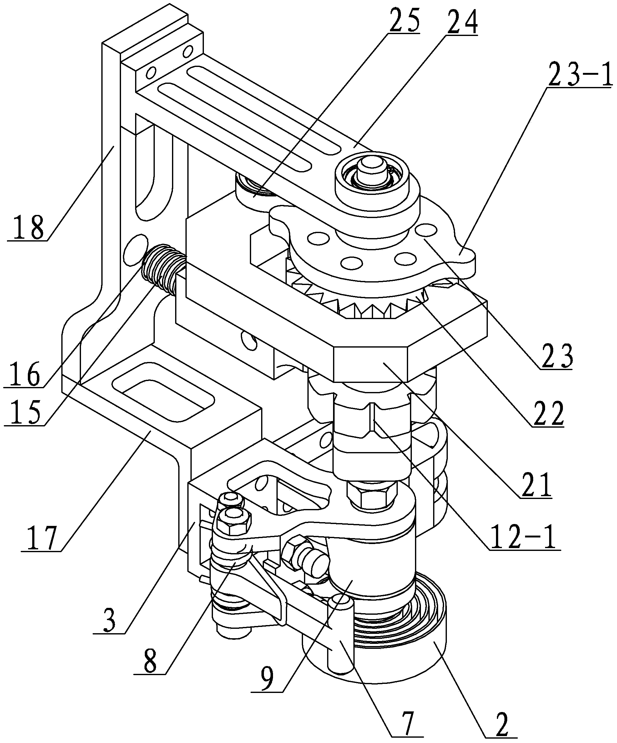
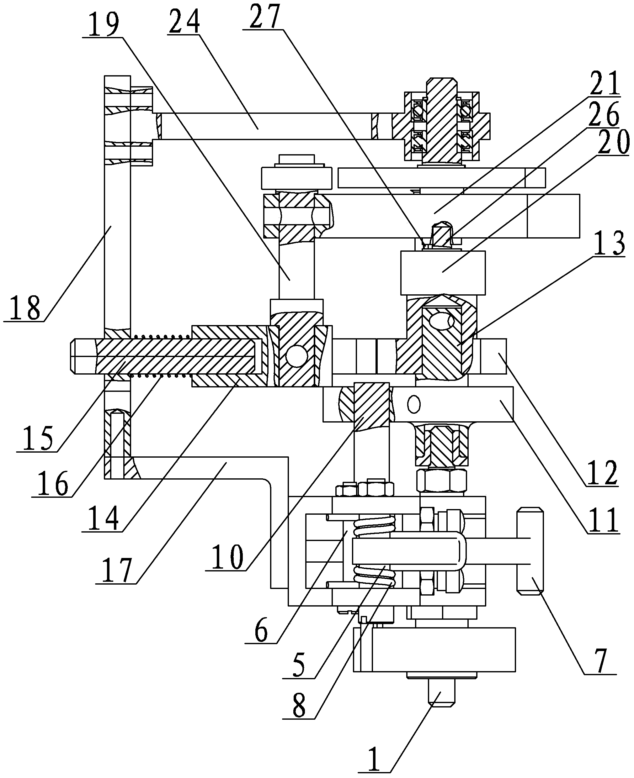
[0014] Specific implementation mode one: combine Figure 1-Figure 3 Describe this embodiment, this embodiment is an intermittent spring unfolding hinge deceleration mechanism, which includes a hinge assembly, the hinge assembly includes a hinge central shaft 1, a driving scroll spring 2, a male hinge 3, a female hinge 4, and a torsion spring rod 5. Torsion spring lever 6, lock lever 7, pressure lever spring 8 and hinge sleeve 9, the male hinge 3 and the female hinge 4 are rotatably arranged on the hinge central axis 1, and the hinge sleeve 9 is arranged on the male hinge 3 and the female hinge On the hinge central axis 1 between the hinges 4, the torsion spring bar 5 is vertically arranged on the male hinge 3, and one end of the lock bar 7 is arranged on the torsion spring bar 5, and the other end of the lock bar 7 can be locked under the hinge locked state. Set up on the female hinge 4, one end of the pressure bar spring 8 is set on the torsion spring bar 5, the other end of ...

specific Embodiment approach 2

[0025] Specific implementation mode two: combination figure 1 The present embodiment will be described. A plurality of flanges 23-1 are provided on the outer edge of the cam 23 of the present embodiment. Such arrangement facilitates intermittent release of energy in the energy storage scroll spring 20 . Other compositions and connections are the same as in the first embodiment.

specific Embodiment approach 3

[0026] Specific implementation mode three: combination figure 1 The present embodiment will be described. The number of the plurality of flanges 23 - 1 in the present embodiment is two, four or six. Such setting makes it easy to select an appropriate intermittent release frequency according to the actual situation of solar wing deployment, wherein the more the number of flanges 23-1, the faster the intermittent release. Other compositions and connections are the same as those in Embodiment 1 or Embodiment 2.


PUM


Abstract

The invention discloses an intermittent spring expansion hinge reducing mechanism and relates to a hinge reducing mechanism. The invention aims at solving the problem that locking impact is likely to occur at the expansion end of an existing solar wind expansion hinge driven by a volute spiral spring due to overlarge expansion speed. The intermittent spring expansion hinge reducing mechanism comprises a hinge assembly and a switching assembly, a locking assembly and a sourceless automatic self-unlocking mechanism which are arranged at the upper end of the hinge assembly from bottom to up in sequence. On the premise that the exiting expansion hinge structure remains the same, the continuous rotating of a hinge without the reducing mechanism is converted to the following motion: rotating-locking-unlocking-rotating; in the short locking period, the hinge stops rotating, therefore, the original continuous rotating becomes an intermittent motion and the locking impact force is reduced; the intermittent spring expansion hinge reducing mechanism is used for speed reducing of the solar wing expansion hinge.

Description

technical field [0001] The invention relates to a deceleration mechanism, in particular to a deceleration component for reducing the locking impact of a solar wing deployment hinge. Background technique [0002] The unfolding hinge has the functions of hinge, unfold and lock, and is widely used in space deployable mechanisms, such as satellites, planetary exploration vehicles, and solar wing panels of space stations. These mechanisms generally have the characteristics of large size, light weight, and are difficult to attenuate once they are excited. Therefore, these mechanisms require that shocks be avoided as much as possible during deployment to prevent damage to components caused by resonance or affect working conditions. The hinge is mainly composed of a male hinge and a female hinge, a female hinge and a vortex spring, and the male hinge and the female hinge are fixedly connected to the root of the spacecraft and the solar wing sails respectively. The deployment end of...

Claims


Application Information

Patent Timeline
IPC IPC(8): F16C11/12F16C11/10
Inventor 郭宏伟李忠杰刘荣强邓宗全
Owner HARBIN INST OF TECH
Why Eureka
Try Eureka