Intermittent type spring unfolding hinge speed reduction mechanism

A deceleration mechanism and intermittent technology, applied in the direction of pivot connection, etc., can solve the problems of high deployment speed and locking shock, and achieve the effect of avoiding excessive deployment speed.

Inactive Publication Date: 2017-05-03
崔立晶
View PDF0 Cites 3 Cited by
  • Summary
  • Abstract
  • Description
  • Claims
  • Application Information

AI Technical Summary

Problems solved by technology

[0003] The purpose of the present invention is to solve the problem that the existing solar wing deployment hinge driven by scroll springs is prone to locking impact due to excessive deployment speed, and to provide an intermittent spring deployment hinge deceleration mechanism

Method used


Image

  • Intermittent type spring unfolding hinge speed reduction mechanism
  • Intermittent type spring unfolding hinge speed reduction mechanism

Examples


Embodiment Construction

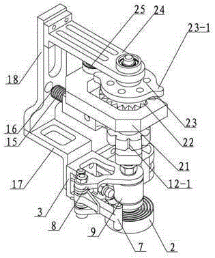
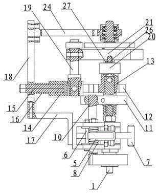
[0013] combine figure 1 , figure 2 , an intermittent spring hinge deceleration mechanism in this embodiment, which includes a hinge assembly, the hinge assembly includes a hinge central axis 1, a driving scroll spring 2, a male hinge 3, a female hinge 4, a torsion spring rod 5, a torsion spring Gear lever 6, lock lever 7, pressure lever spring 8 and hinge sleeve 9, male hinge 3 and female hinge 4 are rotatably arranged on hinge central axis 1, and hinge sleeve 9 is arranged between male hinge 3 and female hinge 4 On the central axis l of the hinge, the torsion spring rod 5 is vertically arranged on the male hinge 3, one end of the lock rod 7 is arranged on the torsion spring rod 5, and the other end of the lock rod 7 can be set on the female hinge when the hinge is locked. 4, one end of the compression rod spring 8 is arranged on the torsion spring rod 5, the other end of the compression rod spring 8 is arranged on the lock rod 7, the driving scroll spring 2 is arranged on t...


PUM


Abstract

The invention relates to a hinge speed reduction mechanism, in particular to an intermittent type spring unfolding hinge speed reduction mechanism, and aims to solve the problem that locking impact is easily caused by extremely high unfolding speed as the tail end is unfolded by an existing solar wing unfolding hinge driven by a volute spiral spring. The intermittent type spring unfolding hinge speed reduction mechanism comprises a hinge assembly, an adaptor assembly, a locking assembly and a passive automatic unlocking mechanism, wherein the adaptor assembly, the locking assembly and the passive automatic unlocking mechanism are arranged at the upper end of the hinge assembly in sequence from bottom to top. The invention provides the intermittent type spring unfolding hinge speed reduction mechanism which enables the continuous rotation of a hinge without the speed reduction mechanism to be converted into the following motions: rotation, locking, unlocking and rotation on the premise of not changing the existing unfolding hinge structure. The hinge does not rotate within a transient locking time period, so that the original continuous rotation of the hinge is converted into an intermittent motion, and the locking impact force is reduced. The intermittent type spring unfolding hinge speed reduction mechanism is used for speed reduction of the solar wing unfolding hinge.

Description

technical field [0001] The invention relates to a deceleration mechanism, in particular to a deceleration component for reducing the locking impact of a solar wing deployment hinge. Background technique [0002] The unfolding hinge has the functions of hinge, unfold and lock, and is widely used in space deployable mechanisms, such as satellites, planetary exploration vehicles, and solar wing panels of space stations. These mechanisms generally have the characteristics of large size, light weight, and are difficult to attenuate once they are excited. Therefore, these mechanisms require that shocks be avoided as much as possible during deployment to prevent damage to components caused by resonance or affect working conditions. The hinge is mainly composed of a male hinge and a female hinge, a female hinge and a vortex spring, and the male hinge and the female hinge are fixedly connected to the root of the spacecraft and the solar wing sails respectively. The deployment end of...

Claims


Application Information

Patent Timeline
Patent Type & Authority Applications(China)
IPC IPC(8): F16C11/04F16C11/12
Inventor 崔立晶
Owner 崔立晶
Why Eureka
Try Eureka