Uplink DMRS transmitting method, device and system/ Transmitting method, device and system used for uplink DMRS

A technology for demodulating reference signals and sending methods, which is applied to the separation device of the transmission path, transmission system, multi-frequency code system, etc., and can solve the problems of large time-frequency resource overhead and other issues

Active Publication Date: 2014-07-23
ZTE CORP
View PDF5 Cites 221 Cited by
  • Summary
  • Abstract
  • Description
  • Claims
  • Application Information

AI Technical Summary

Problems solved by technology

[0015] The present invention provides a method, device and system for sending an uplink demodulation reference si...

Method used


Image

  • Uplink DMRS transmitting method, device and system/ Transmitting method, device and system used for uplink DMRS
  • Uplink DMRS transmitting method, device and system/ Transmitting method, device and system used for uplink DMRS
  • Uplink DMRS transmitting method, device and system/ Transmitting method, device and system used for uplink DMRS

Examples


Embodiment 1

[0135] First, Embodiment 1 of the present invention will be described with reference to the accompanying drawings.

[0136] An embodiment of the present invention provides a method for sending an uplink demodulation reference signal, and using this method to complete the process of sending an uplink demodulation reference signal is as follows: Figure 5 shown, including:

[0137] Step 501, the base station configures resources or patterns or parameter sets required for sending uplink DMRS for the user terminal;

[0138] In this step, the resource or pattern (pattern) or parameter set includes: a time domain position, a frequency domain position, and a hopping mode.

[0139] Among them, the time domain position includes:

[0140] When the length of the uplink symbol cyclic prefix is ​​a normal length, the time domain position is specifically: the 1st slot and / or the 4th OFDM symbol of the 2nd slot of the subframe containing the uplink DMRS; or, the 4th OFDM symbol containing ...

Embodiment 2

[0154] Embodiment 2 of the present invention will be described below with reference to the accompanying drawings.

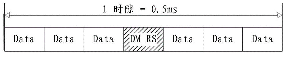
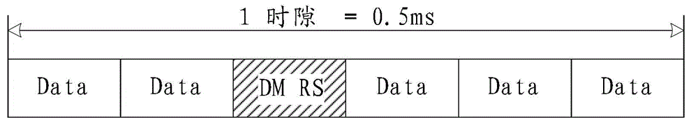
[0155] The base station configures the subframe configuration or period of the uplink DMRS for the user terminal through high-level signaling, as shown in Table 2, Table 3, or Table 4 below. Among them, when the uplink DMRS subframe configuration index in Table 2 is 0, the period is 0.5, which means that there are 2 DMRS time domain symbols in a subframe, and the position of the time domain symbols is the same as that in the Rel-8 / 9 / 10 / 11 standard The position of the uplink DMRS time domain symbols is the same for backward compatibility with Rel-8 / 9 / 10 / 11 UEs. When the uplink DMRS subframe configuration index is 1, it means that there is only one uplink DMRS time domain symbol in a subframe; when the subframe configuration index is 2, it means that the uplink DMRS cycle is 2, and the offset is 0, which means the first One subframe has a DMRS, and the second subf...

Embodiment 3

[0169] The base station configures at least one resource or pattern or parameter set required for sending the uplink DMRS for the user terminal through high-layer signaling, and selects one of the at least one resource or pattern or parameter set through the bit field in the downlink control information.

[0170] Taking the UE as an example to describe the user terminal, two DMRS patterns are configured for the UE. The first pattern is the same as the uplink DMRS pattern of Rel-8 / 9 / 10 / 11 for backward compatibility with UEs of lower versions. That is, in the case of a regular CP, the uplink DMRS sequence is placed on all subcarriers of the 4th OFDM symbol in each slot of the subframe, and in the case of an extended CP, all subcarriers of the 3rd OFDM symbol in each slot of the subframe Place the uplink DMRS sequence on the carrier; the second pattern is the uplink DMRS pattern configured for small cell or NCT, and configure the uplink DMRS in combination with the uplink DMRS sub...


PUM


Abstract

The invention relates to the field of communication, provides an uplink DMRS (Demodulation Reference Signal) transmitting method, device and system and solves the problem that the time-frequency resource overhead of the uplink demodulation reference signal is excessive. The method comprises the steps that a base station configures a resource, a pattern or a parameter set required for transmitting the uplink DMRS for a user terminal; and the base station transmits or indicates the resource, the pattern or the parameter set required for transmitting the uplink DMRS to the user terminal via a bit domain or a high-level signaling of downlink control information. The resource, the pattern or the parameter set comprises a time domain position, a frequency domain position, a subframe configuration or a cycle, and a hopping mode. The technical scheme is applicable to a long term evolution system, and an uplink DMRS transmitting mechanism with the low time-frequency resource overhead is realized.

Description

technical field [0001] The present invention relates to the communication field, in particular to a method, device and system for sending an uplink demodulation reference signal (Demodulation Reference Signal, DMRS for short). Background technique [0002] The uplink physical channels of the Long Term Evolution system (LTE, Long Term Evolution) include Physical Random Access Channel (PRACH, Physical Random Access Channel), Physical Shared Channel (PUSCH, Physical uplink shared channel), Physical Uplink Control Channel (PUCCH, Physical Uplink Control Channel). The uplink scheduling information (Uplink Scheduling Information) for the PUSCH is sent by the base station to a target user terminal (UE, User Equipment) through a physical downlink control channel (Physical Downlink Control Channel, PDCCH for short). The uplink scheduling information includes: resource allocation related to the physical uplink shared channel, modulation and coding scheme, DMRS cyclic shift (Cyclic Sh...

Claims


Application Information

Patent Timeline
IPC IPC(8): H04L1/00H04L1/06H04L27/26
CPCH04L5/0094H04L5/0007H04L5/0051
Inventor 王瑜新关艳峰孙云锋陈艺戬李书鹏陈宪明罗薇
Owner ZTE CORP
Why Eureka
Try Eureka