[0007]The present invention is directed to systems and methods which utilize antenna pattern or antenna
beam scanning (e.g., forming antenna patterns and
processing antenna beam signals in a scanning sequence) techniques to provide communication of
payload traffic (e.g., data packets). A base station radio (e.g.,
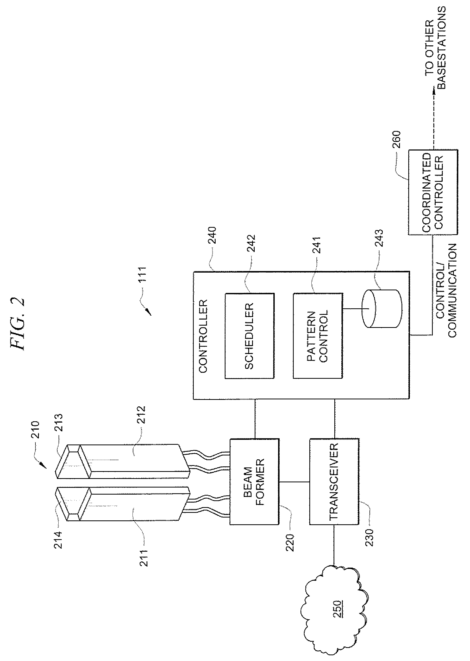
transceiver) is provided wireless communication links with a plurality of stations (e.g., subscriber stations) for communication of payload traffic between the base station and stations using a succession of antenna patterns according to embodiments of the invention. The wireless communication links are preferably provided through the use of a plurality of directional antenna patterns which are chosen from a superset of predefined antenna patterns available at the base station. The plurality of directional antenna patterns are scanned in succession, such as randomly, quasi-randomly, sequentially, or according to a schedule (e.g. timed, weighted, etcetera), to provide communications throughout the service area with the stations disposed therein. The use of predefined antenna patterns reduces
processing requirements and delays associated with forming antenna patterns for use in providing communications, while facilitating the use of directional antenna patterns providing advantages with respect to interference, capacity, range, etcetera.
[0008]In operation according to a preferred embodiment, neither detailed nor perfect
channel state information is required from the stations in order to utilize directional antenna patterns. For example, as the base station scans the directional antenna patterns forming the currently chosen plurality of directional antenna patterns, stations may provide information identifying a best (e.g., highest
signal to
interference ratio (SIR), highest receive
signal strength indicator (RSSI), lowest
bit error rate (BER), etcetera) one of the directional antenna patterns for use with that station, such as through the use of a
ranging protocol. Feedback of antenna
pattern selection information requires less overhead and can be accomplished more expeditiously than feedback of complete channel state information required to uniquely form a directional antenna pattern for a station.
[0009]Embodiments of the invention utilize an antenna pattern scheduler to implement antenna pattern scanning and traffic timing. For example, an antenna pattern scheduler of embodiments of the invention invokes a desired succession of antenna patterns for the base station and ensures that data
packet transmission and reception associated with stations for which each particular antenna pattern has been selected coincide with the antenna pattern succession. Antenna pattern schedulers may invoke algorithms to control the succession of antenna patterns, the active times of antenna patterns, the periodicity or repetition of particular antenna patterns, etcetera in order to provide various features or benefits. For example, desired quality of sendee (QoS) may be facilitated with respect to one or more station by an antenna pattern scheduler of an embodiment of the invention, such as by more frequent scheduling of an antenna pattern determined to be best with respect to the station for which a high QoS is desired. An antenna pattern scheduler may control scanning of the antenna patterns such that the illumination (as may be provided by one or more antenna beams) time of one or more portions of a service area associated with higher traffic is greater than the illumination times of other portions of the service area, thereby providing increased
throughput. Additionally or alternatively, intra-network interference mitigation may be facilitated through antenna pattern succession control by an antenna pattern scheduler of an embodiment of the invention.
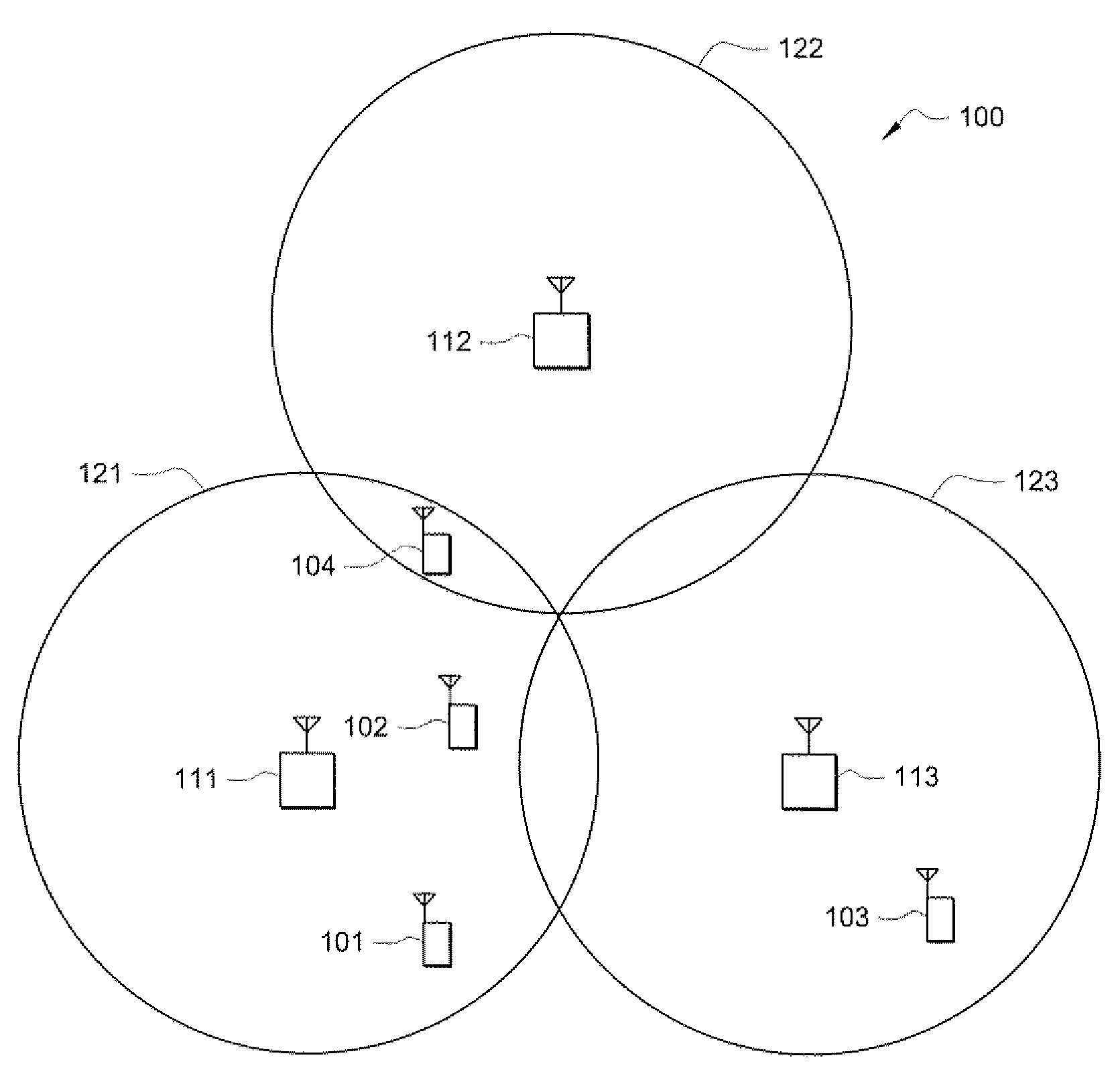
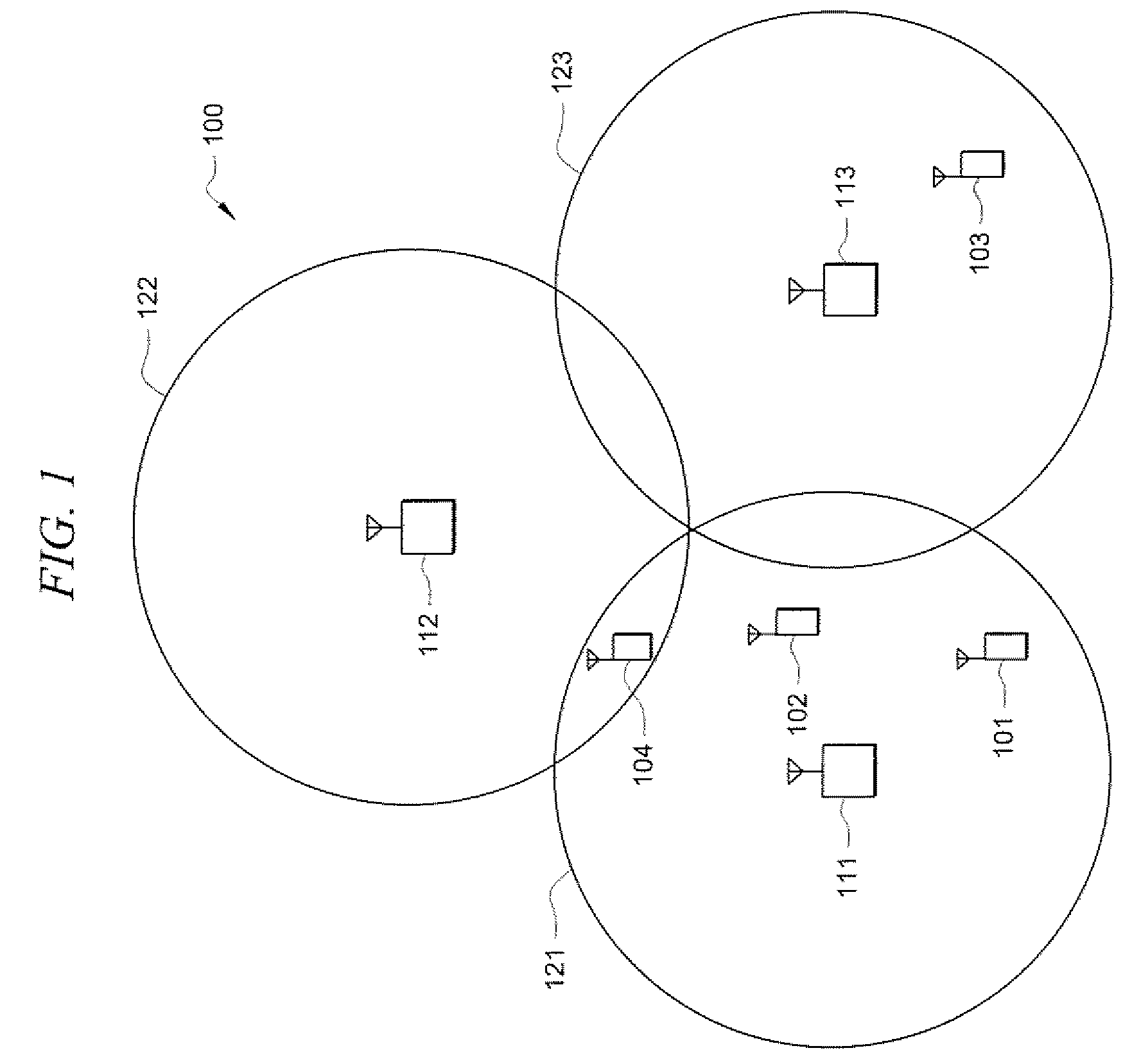
[0010]Cooperative scheduling with respect to a plurality of base stations is provided according to embodiments of the invention. For example, a
network scheduler (e.g., a master one of the aforementioned antenna pattern schedulers coupled to antenna pattern schedulers of other base stations or a centralized scheduler coupled to the antenna pattern schedulers of base stations) may be used to coordinate the succession of antenna patterns for a plurality of base stations in a communication network. By coordinating the antenna pattern successions, intra-network interference may be avoided, such as by selection of antenna patterns for use at adjacent base stations, or base stations within
line of sight of each other, which do not result in interference (e.g., non-overlapping, have orthogonal attributes, do not present wave fronts directed at one another, etcetera).
[0011]Selection of the plurality of directional antenna patterns used by a base station is preferably adjusted from time to time, such as based upon environment, usage patterns, etcetera. For example, an initial subset of directional antenna patterns may be chosen from the superset of predefined antenna patterns available at the base station as a set of antenna patterns commonly found to provide adequate communications, a set of antenna patterns likely to provide desired operation with respect to an expected operational environment, etcetera. Such an initial selection may, for example, provide an even distribution of directional antenna patterns azimuthally about a base station location. However, in operation of the particular base station it may be discovered that user stations and / or communications loading is not uniformly distributed throughout the sendee area. A controller of the present invention may operate to adapt selection of the directional antenna patterns so as to provide fewer, perhaps broader beam, antenna patterns covering the less used portions of the service area and more, perhaps narrower beam, antenna patterns covering the more used portions of the service area. Accordingly,
lime scanning and / or serving less used portions of the service area may be minimized while time scanning and / or
seizing more used portions of the service area may be increased, thus providing increased capacity and performance.
[0012]Embodiments of the present invention provide scheduling of communications using the aforementioned succession of antenna patterns to optimize service
area coverage and
system capacity. Through the use of a one
data stream (it being understood that such a
data stream my comprise a multiple access
data stream carrying data associated with a plurality of nodes) to many antenna pattern configuration, and by leveraging the use of directional antenna patterns to reduce interference while increasing service
area coverage and / or
system capacity, embodiments of the present invention provide a relatively low cost solution, both in equipment costs and control overhead and processing costs.

