
Method and system for angle measurement

a technology of angle measurement and measurement method, applied in the direction of angle measurement, material analysis, instruments, etc., can solve the problem that the device provides limited angular resolution, and achieve the effect of improving accuracy, high measurement accuracy, and reducing the number of elements used in the analysis phas

Active Publication Date: 2010-04-13
TRIMBLE JENA
View PDF26 Cites 55 Cited by
  • Summary
  • Abstract
  • Description
  • Claims
  • Application Information

AI Technical Summary

Benefits of technology

The present invention provides an angle measurement device with high accuracy using a multi-element, high-resolution imaging device. The device is affordable and can be incorporated in small systems. The device includes a light source, a patterned member with a periodic optical variation, and an imaging device with photosensitive elements arranged in an array configuration. The device can measure the rotation angle of the patterned member by analyzing the spatially modulated optical waveform. The use of a wide area sensor array allows for convenient identification of the center of rotation and effective correction of eccentricity and alignment errors. The technical effects of the present invention include improved accuracy, affordability, and ease of use in small systems.

Problems solved by technology

However, this device provides limited angular resolution.

Method used


Image

  • Method and system for angle measurement
  • Method and system for angle measurement
  • Method and system for angle measurement

Examples


Embodiment Construction

[0035]Embodiments of the present invention provide methods and systems for angle measurement characterized by improved accuracy in comparison to conventional systems. In a particular embodiment, a small, compact, highly accurate, and inexpensive angle measurement device is provided.

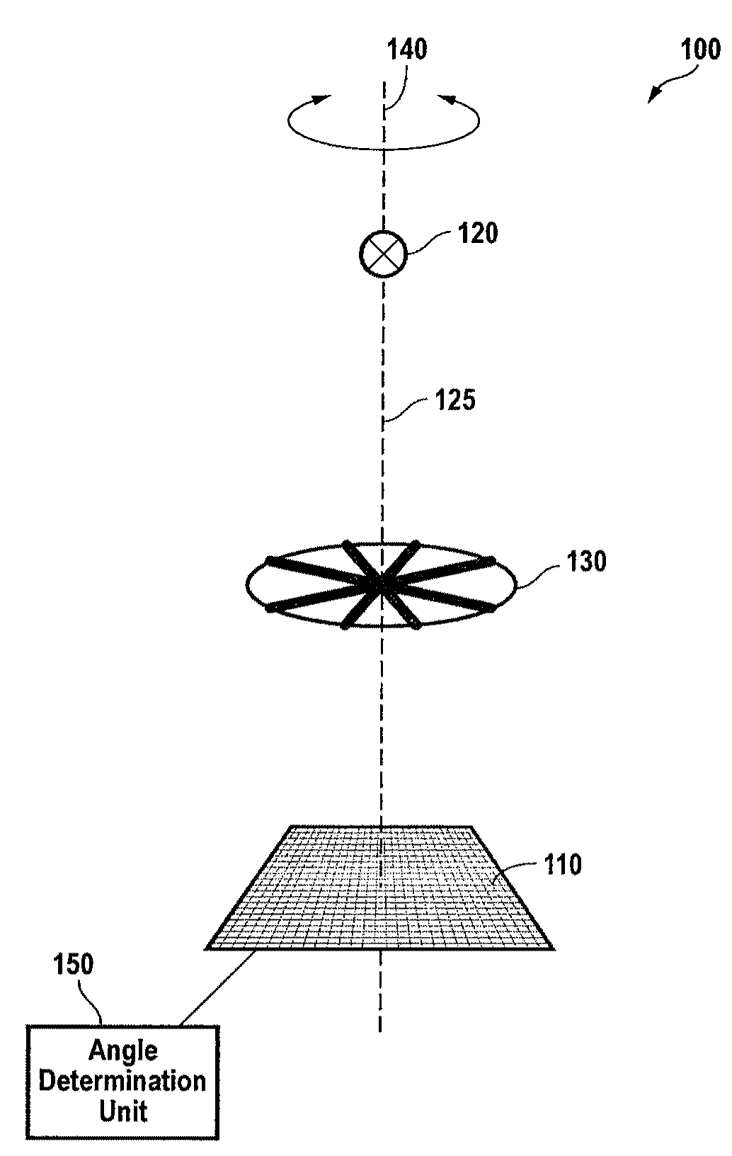
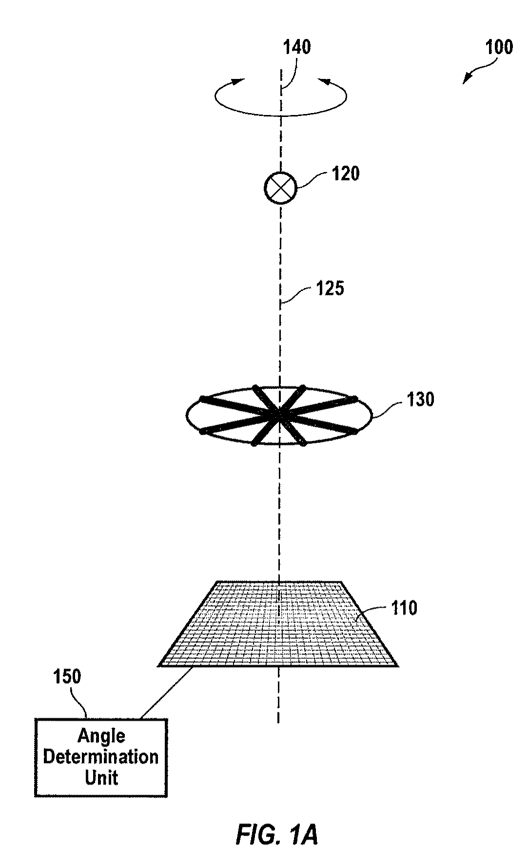
[0036]FIG. 1A is a simplified schematic diagram illustrating an angle measurement device according to an embodiment of the present invention. As illustrated in FIG. 1A, the angle measurement device 100 includes a light source 120. The light source is typically a light emitting diode (LED) or other suitable source of optical radiation. In a particular embodiment, the light source is a small (e.g., point) source LED. A representative example is model ELC 645-29-5 available from EPIGAP GmbH of Berlin, Germany. The ELC 645-29-5 is a 645 nm LED that provides a light source diameter of 150 μm without the use of supplemental optics. Optical elements associated with the light source (e.g., reflectors, lenses, and...


PUM


Abstract

An angle measurement device includes a light source configured to emit light along an optical path and a patterned member positioned along the optical path and configured to rotate about an axis of rotation. The patterned member includes a periodic optical variation. Light passing through the patterned member provides a spatially modulated optical waveform. The angle measurement device also includes an imaging device positioned along the optical path and including a plurality of photosensitive elements disposed in an array configuration. The imaging device is configured to receive the spatially modulated optical waveform and provide a signal associated with light intensity at each of the plurality of photosensitive elements. The angle measurement device further includes an angle determination unit coupled to the imaging device and configured to compute a rotation angle of the patterned member based on a reference waveform and the provided signal.

Description

CROSS-REFERENCES TO RELATED APPLICATIONS[0001]This application is a continuation-in-part of commonly-owned, co-pending PCT Patent Application No. PCT / EP2008 / 052179, filed Feb. 22, 2008 entitled “Absolute Angle Encoder,” the entire disclosure of which is hereby incorporated by reference.BACKGROUND OF THE INVENTION[0002]The present invention relates generally to a method and system for measuring angles. Merely by way of example, the invention has been applied to an angle measurement device useful for determining a rotation angle. In a particular embodiment, a system for measuring rotation angles is utilized in a surveying instrument. However, embodiments of the present invention are not limited to this particular application and may be utilized in a variety of measurement systems.[0003]Angle encoders, such as absolute and incremental angle encoders, have been employed for angular measurements in machine tools, drive technology, automotive electronics, and the like. An example of an an...

Claims


Application Information

Patent Timeline
Patent Type & Authority Patents(United States)
IPC IPC(8): G01B11/26
CPCG01D5/3473
Inventor VOGEL, MICHAELGLIMM, ANDREAS
Owner TRIMBLE JENA
Learn More