

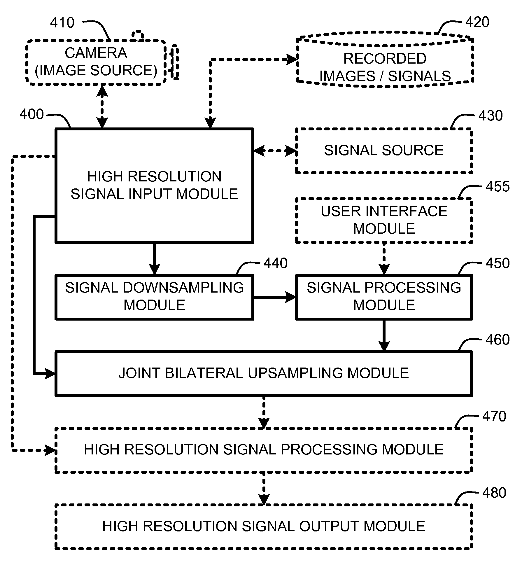
Joint bilateral upsampling
- Summary
- Abstract
- Description
- Claims
- Application Information
AI Technical Summary
Benefits of technology
Problems solved by technology
Method used
Image

Examples
Embodiment Construction
[0021]In the following description of the preferred embodiments of the present invention, reference is made to the accompanying drawings, which form a part hereof, and in which is shown by way of illustration specific embodiments in which the invention may be practiced. It is understood that other embodiments may be utilized and structural changes may be made without departing from the scope of the present invention.
[0022]1.0 Exemplary Operating Environments:
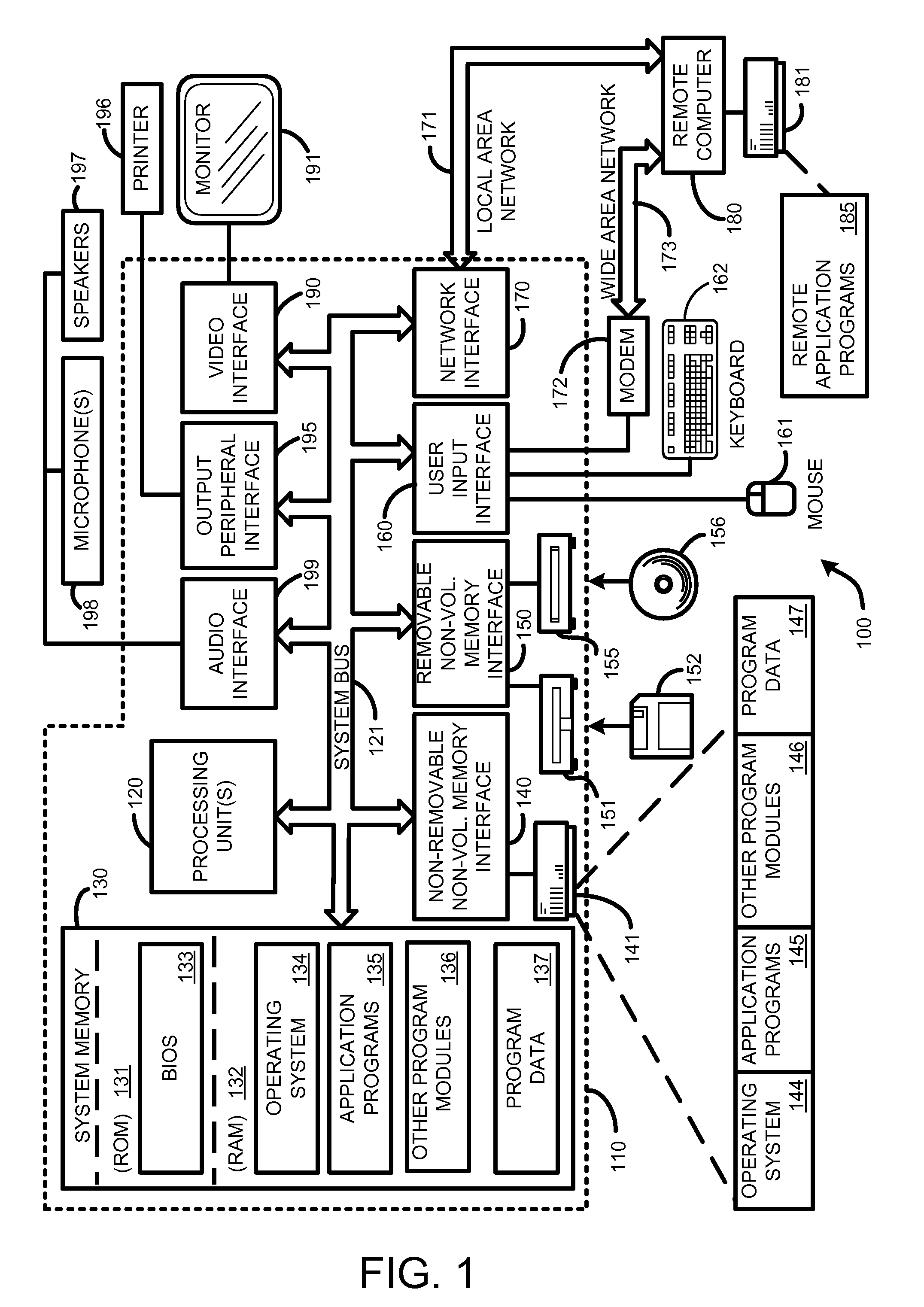
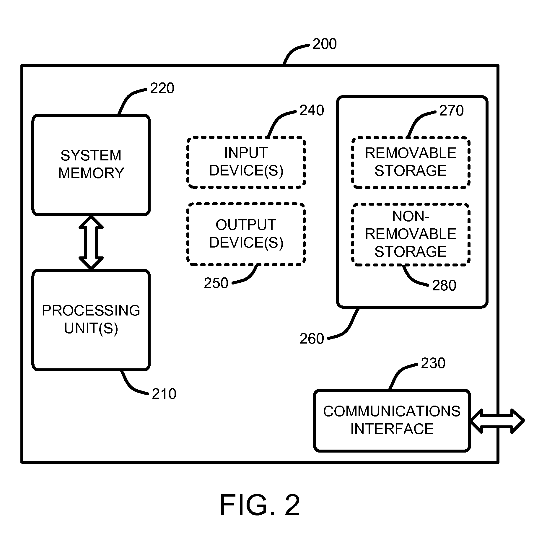
[0023]FIG. 1, FIG. 2, and FIG. 3 illustrate various examples of suitable computing environments on which various embodiments and elements of a “Joint Bilateral Upsampler,” (JBU) as described herein, may be implemented.
[0024]For example, FIG. 1 illustrates an example of a general computing system environment 100. The computing system environment 100 is only one example of a suitable computing environment and is not intended to suggest any limitation as to the scope of use or functionality of the invention. Neither should the comp...
PUM
 Abstract
Description
Claims
Application Information