Novel dimmable shutter

A blind, a new type of technology, applied in the field of new adjustable blinds, can solve the problems of ventilation and anti-theft effects that cannot meet customer needs at the same time, and achieve the effect of ingenious structural design, avoiding trouble and inconvenience, and convenient assembly

Inactive Publication Date: 2014-07-30
常州天经新型建材有限公司
View PDF8 Cites 6 Cited by
  • Summary
  • Abstract
  • Description
  • Claims
  • Application Information

AI Technical Summary

Problems solved by technology

However, the blades of blinds on the market only have one function, and cannot meet the needs of customers in terms of ventilation and anti-theft effects at the same time. The blades of the present invention can be rolled up or turned 90°, and are anti-theft. On the basis of ordinary blinds In addition, the ventilation and lighting properties are greatly improved to meet a wider market demand

Method used


Image

  • Novel dimmable shutter
  • Novel dimmable shutter
  • Novel dimmable shutter

Examples


Embodiment 1

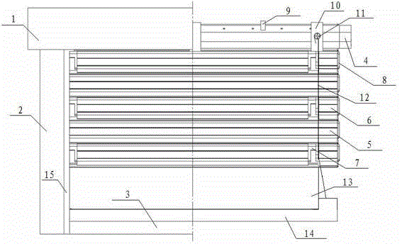
[0029] combined with figure 1 with attached figure 2 , the present invention proposes a new type of dimmable blinds, including a top frame 1 and a side frame 2, a rotating shaft 4 is arranged inside the top frame 1, and the side frames 2 are respectively located under the left and right sides of the top frame, so The rotating shaft 4 is connected with a whole row of blades 5 that rotate and move up and down, and the two sides of the blades 5 are respectively embedded in the side frame 2 .

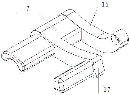
[0030] like Figure 1 to Figure 7 As shown, movable blades 6 are arranged at intervals in the blades of this embodiment, and the movable blades 6 are divided into three sections, the flipped blade segment 6-1 between the frames on both sides, the connecting blade segment 6 located on both sides of the flipped blade segment -2, the turning blade segment 6-1 is isolated from the connecting blade segment 6-2 by a connecting piece 7, and the connecting piece 7 is fixed at both ends of the tu...

Embodiment 2

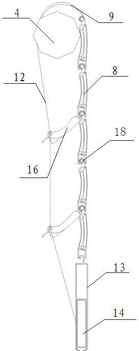
[0036] See attached Figure 8 , On the basis of Embodiment 1, all the blades 5 are replaced with movable blades 6, so that each blade can be rotated and opened under the action of the stay cord 12. When the whole movable blade 6 fell completely, it formed a closed state under the action of the counterweight 14; continue to rotate the rotating shaft 4, and the stay cord 12 pulls the connecting piece 7, and the movable blade 6 is opened with the connecting piece 7. When the connecting rope part 16 is opened Stop when running into the notch of retaining bar 15.

[0037] In this embodiment, the inside of the blade 5 is provided with fillers, which have the effects of sound insulation, heat insulation and heat preservation.

[0038] In the present invention, the counterweight 14 can be one, two, three or even more pieces, and the counterweight 14 can be completely arranged inside the cavity of the decorative profile 13, or can be partially butted as described in Embodiment 1 .

...


PUM


Abstract

The invention relates to a novel dimmable shutter. The novel dimmable shutter comprises a rotating shaft, a whole column of blades connected to the rotating shaft, a decorative section, a balancing weight and a draw cord, wherein at least one movable blade is arranged in the blades and is divided into three sections, namely an overturning blade section and connecting blade sections positioned on two sides of the overturning blade section, adjacent sections are connected through a connecting piece, and the movable blade and connecting piece are together inserted on a thin shaft; the balancing weight vertically moves in the decorative section; one end of the draw cord is fixed to the rotating shaft, and the other end of the draw cord is sequentially connected with all connecting pieces from top to bottom until the balancing weight. When the blades of the shutter are closed, the rotating shaft is continuously rotated, the draw cord drags a connecting piece connected with the draw cord to move upwards, and the overturning blade section is driven to overturn. The novel dimmable shutter is skillful in structural design; the arranged movable blade can be continuously and optionally opened when a window is closed for preventing theft, and the effects of ventilating and the like are achieved.

Description

technical field [0001] The invention relates to a novel dimmable blind with blades that can be rolled up and turned over, which is suitable for residential buildings, commercial buildings and other public buildings. Background technique [0002] Blinds have been widely used in public buildings such as modern housing and commercial buildings. They use the concave-convex direction of the blades to block the outside line of sight and lighting, and at the same time block the top-to-bottom outside line of sight; and it is easy to clean. However, the blades of blinds on the market only have one function, and cannot meet the needs of customers in terms of ventilation and anti-theft effects at the same time. The blades of the present invention can be rolled up and turned 90°, and are anti-theft. On the basis of ordinary blinds In terms of ventilation and lighting, the ventilation and lighting properties are greatly improved to meet a wider market demand. Contents of the invention ...

Claims


Application Information

Patent Timeline
Patent Type & Authority Applications(China)
IPC IPC(8): E06B9/28E06B7/086
Inventor 张学录黄小青
Owner 常州天经新型建材有限公司
Why Eureka
Try Eureka