
A display device and its manufacturing method

A technology of a display device and a display area, applied in the field of communication, can solve the problem that the observer cannot see the black border of the frame area and the like

Active Publication Date: 2016-10-05
YULONG COMPUTER TELECOMM SCI (SHENZHEN) CO LTD
View PDF7 Cites 0 Cited by
  • Summary
  • Abstract
  • Description
  • Claims
  • Application Information

AI Technical Summary

Problems solved by technology

[0003] Aiming at the deficiencies of the prior art, the object of the present invention is to provide a display device and its manufacturing method, the optical part refracts the light entering the second light-transmitting part and shoots it to the observer, so that the observer cannot see the black border of the frame area , which aims to solve the problem that the observer sees the black border formed by the border area when the display device displays

Method used


Image

  • A display device and its manufacturing method
  • A display device and its manufacturing method
  • A display device and its manufacturing method

Examples


Embodiment Construction

[0029] In order to make the object, technical solution and beneficial effects of the present invention more clear, the present invention will be further described in detail below in conjunction with the accompanying drawings and embodiments. It should be understood that the specific embodiments described here are only used to explain the present invention, not to limit the present invention.

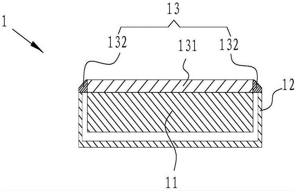
[0030] Such as figure 2 As shown, a display device 1 provided by an embodiment of the present invention includes a display panel 11 and a housing 12 .

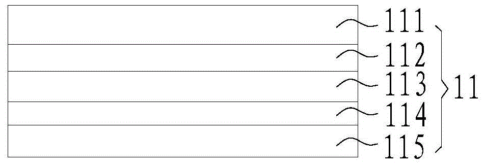
[0031] Such as figure 2 and image 3 As shown, the display panel 11 is disposed in the casing 12 , and the display panel 11 includes an upper polarizer 111 , a color filter 112 , a liquid crystal panel 113 , a lower polarizer 114 and a backlight 115 .

[0032] In this embodiment, the upper polarizer 111 , the color filter 112 , the liquid crystal panel 113 , the lower polarizer 114 and the backlight source 115 are stacked up and dow...


PUM


Abstract

The present invention relates to the field of communication technology, and in particular to a display device and a manufacturing method thereof. A display device includes a casing, a display panel and a light-transmitting cover. The display panel is arranged in the casing to form a display area composed of the display panel and a frame area surrounding the display panel. The light-transmitting cover is closed on the casing to form a display area. On the outer surface of the display device, the light-transmitting cover has a first light-transmitting part and a second light-transmitting part. The first light-transmitting part corresponds to the display area, and the second light-transmitting part corresponds to the frame area. The light emitted by the display panel Light is emitted to the outside from the first light-transmitting part and the second light-transmitting part, wherein an optical part is provided on the outer surface of the second light-transmitting part, and the optical part is used to change the light emitted by the display panel and passing through the second light-transmitting part. The direction of the light emitted from the second light-transmitting part is consistent with the direction of the light emitted from the first light-transmitting part.

Description

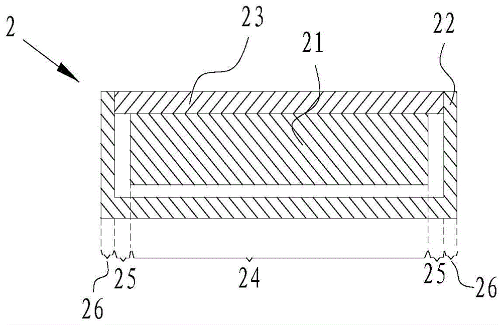
technical field [0001] The present invention relates to the field of communication technology, in particular to a display device and a manufacturing method thereof. Background technique [0002] Such as figure 1 As shown, the display device 2 includes a display panel 21, a housing 22 and a light-transmitting cover plate 23. The housing 22 wraps the display panel 21 and the light-transmitting cover plate 23. The total area of ​​the display device 2 includes a display area 24, a frame area 25 and a thickness of the housing. Area 26 and frame area 25 are used for arranging the required wires of the display panel 21. The non-display area of ​​the display device 2 is the sum of the frame area 25 and the shell thickness area 26. When the display panel 21 displays a picture, the observer will see that the frame area 25 is formed The black border affects the experience. Contents of the invention [0003] Aiming at the deficiencies of the prior art, the object of the present inve...

Claims


Application Information

Patent Timeline
Patent Type & Authority Patents(China)
IPC IPC(8): G02F1/13G02F1/1335G02F1/13357
CPCG06F1/16G09F9/00G02B27/095G02B27/12G02F1/133308G02F1/133526G02F1/133331G02F1/133388G02F1/13336G02F2203/24
Inventor 肖健
Owner YULONG COMPUTER TELECOMM SCI (SHENZHEN) CO LTD
Learn More