
A display substrate and its preparation method and display panel

A display substrate, non-display technology, applied in the direction of identification devices, instruments, etc., can solve problems such as poor display screens, achieve borderless display, improve quality, and ensure quality

Active Publication Date: 2022-04-19
BOE TECH GRP CO LTD
View PDF0 Cites 0 Cited by
  • Summary
  • Abstract
  • Description
  • Claims
  • Application Information

AI Technical Summary

Problems solved by technology

[0004] The invention aims at the problem that the manufacturing of metal wires or filling the resin in the opening of the substrate leads to the problem that the display screen is defective during the preparation, and provides a display substrate and its preparation method and display panel

Method used


Image

  • A display substrate and its preparation method and display panel
  • A display substrate and its preparation method and display panel
  • A display substrate and its preparation method and display panel

Examples


Embodiment 1

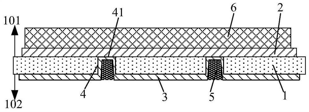
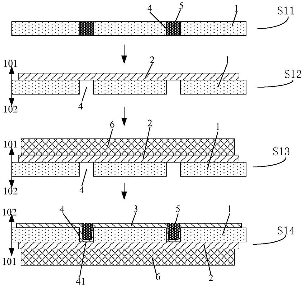
[0039] This embodiment provides a display substrate, such as figure 1 As shown, a substrate 1 is included, and the substrate 1 includes a display side 101 and a non-display side 102 arranged oppositely, and also includes a driving circuit arranged on the display side 101 of the substrate 1 and a binding circuit arranged on the non-display side 102 of the substrate 1, The driving circuit includes a first conductive layer 2 in contact with the substrate 1, the bonding circuit includes a second conductive layer 3 in contact with the substrate 1, a through hole 4 is opened in the substrate 1 through its thickness, and the second conductive layer 3 penetrates The through hole 4 is connected to the first conductive layer 2 ; the through hole 4 is also filled with a resin layer 5 .

[0040] Wherein, the substrate 1 may be a glass substrate or a flexible substrate.

[0041] By making the second conductive layer 3 connect to the first conductive layer 2 through the through hole 4, and...

Embodiment 2

[0055] This embodiment provides a display substrate, which is different from Embodiment 1 in that image 3 As shown, the first conductive layer 2 is connected to the second conductive layer 3 through the via hole 4 .

[0056] In this embodiment, the first conductive layer 2 covers the sidewall of the through hole 4 and extends to the second end opening 42 of the through hole 4; the second end opening 42 is an end of the through hole 4 close to the second conductive layer 3 Opening; the drive circuit also includes a gas conduction layer 7 and a first circuit layer 6, the gas conduction layer 7 and the first circuit layer 6 are arranged on the side of the first conductive layer 2 away from the substrate 1, and the gas conduction layer 7 and the first The circuit layer 6 is arranged away from the substrate 1 in turn; a via hole 71 is opened in the gas conduction layer 7 , and the first conductive layer 2 is connected to the conductive film layer in the first circuit layer 6 throu...

Embodiment 3

[0074] This embodiment provides a display panel, including the display substrate in any one of the above embodiments.

[0075] By using the display substrate in any one of the above-mentioned embodiments, the display panel can not only realize borderless display, but also improve the quality of the display panel.

[0076] The display panel provided by the present invention can be any product or component with display function such as LCD panel, LCD TV, OLED panel, OLED TV, LED panel, LED TV, monitor, mobile phone, and navigator.


PUM


Abstract

The present invention provides a display substrate, a preparation method thereof, and a display panel. The display substrate includes a base, the base includes a display side and a non-display side arranged oppositely, a drive circuit arranged on the display side of the base and a binding circuit arranged on the non-display side of the base, the drive circuit includes a The first conductive layer, the bonding circuit includes a second conductive layer in contact with the substrate, the substrate is provided with a through hole penetrating the thickness of the second conductive layer, and the second conductive layer through the through hole is connected to the first conductive layer; or, the first conductive layer penetrates through The through hole is connected to the second conductive layer; the through hole is also filled with a resin layer. The display substrate can not only prevent the conductive layer in the through hole from falling off, but also prevent the conductive layer in the through hole from generating large stress in the high-temperature preparation process to damage the substrate; and can prevent the resin layer from generating overflow gas in the high-temperature preparation process, or Avoid damage to the driving circuit caused by the overflowing gas generated in the high temperature preparation process of the resin layer.

Description

technical field [0001] The invention belongs to the field of display technology, and in particular relates to a display substrate, a preparation method thereof, and a display panel. Background technique [0002] In recent years, full screen and borderless splicing display have become an important development direction of high-end mobile display; in order to achieve true borderless, it is proposed to realize borderless display technology through substrate front and back technology, that is, the front is the array substrate driver circuit design, and the back is the driver chip And binding circuit design, through punching holes on the substrate, and then filling the holes with metal to realize the connection of front and back circuit signals, and realize no border. [0003] The traditional method of punching holes on the substrate and filling the holes with metal to realize the connection of front and back circuit signals requires making metal wires in the holes to realize the...

Claims


Application Information

Patent Timeline
Patent Type & Authority Patents(China)
IPC IPC(8): G09F9/30
CPCG09F9/30
Inventor 陈昊玄明花郑皓亮张振宇肖丽赵蛟刘冬妮陈亮
Owner BOE TECH GRP CO LTD
Learn More