


Quick Research
Generate reliable direction feasibility study reports for your R&D in just a few steps.

Technical Q&A
Discover and master advanced knowledge NOW. Basics, ideas, possibilities, all at once.

Find Solutions
As an expert in R&D theories, this can generate solutions to your technical problems instantly.

Evaluate Feasibility
Analyze your overall solution with one click, know your potential R&D risks in advance.

Monitor Landscape
Get weekly tech updates, stay abreast of the latest tech innovations and key insights.
Method for producing lens array, and molding mold
A technology of lens array and manufacturing method, which is applied in the direction of lenses, household appliances, and other household appliances, etc., and can solve the problems of long time transfer mold and longer processing time of transfer mold, etc.
- Summary
- Abstract
- Description
- Claims
- Application Information
AI Technical Summary
Problems solved by technology
Method used
Image

Examples
no. 1 approach 〕
[0040] A method of manufacturing the lens array and the like according to the first embodiment of the present invention will be described with reference to the drawings.
[0041] A) Forming mold is master mold
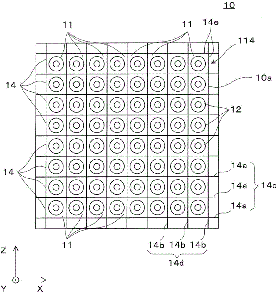
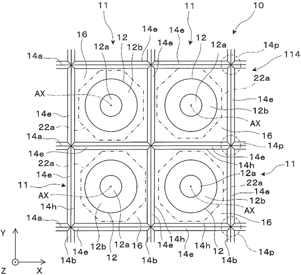
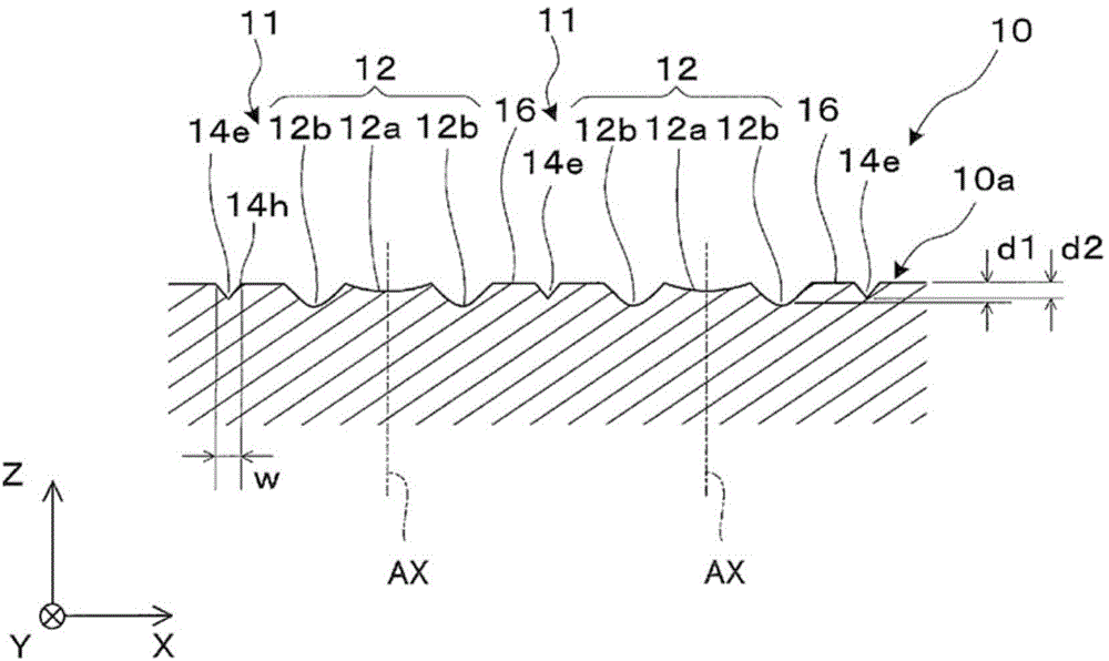
[0042] Such as figure 1 As shown, a master mold 10 , which is a molding die for indirectly manufacturing a lens array, is a plate-shaped member having, for example, a square or circular outline, and has a molding surface 10 a on the end surface side, which is one main surface. The molding surface 10 a has a plurality of minute mold regions 11 divided into grids, and these mold regions 11 are arranged in a matrix extending in the vertical and horizontal XY directions as a whole. Each mold area 11 provided on the molding surface 10a has the same three-dimensional shape within the same outline of a square. A circular cavity portion 12 is provided at the center of each mold area 11, and each mold area 11 is surrounded by a rectangular frame-shaped groove 14 composed of f...
no. 2 approach 〕
[0081] Hereinafter, the manufacturing method etc. of the lens array of 2nd Embodiment are demonstrated. In addition, this embodiment is obtained by partially changing the manufacturing method of the lens array of 1st Embodiment, etc., and the part or item which is not demonstrated especially is the same as the case of 1st Embodiment.
[0082] Such as Figure 13 As shown, a master mold 210 which is a mold for indirectly manufacturing a lens array has a molding surface 210 a on the end surface side which is one main surface. The molding surface 210a has a plurality of minute mold regions 211 divided into triangular scales. The mold regions 211 provided on the molding surface 210a are alternately reversed up and down, but have the same three-dimensional shape within the same outline of the regular triangle. A circular cavity portion 12 is provided at the center of each mold area 211, and the periphery of each mold area 211 is surrounded by a triangular frame-shaped groove 214 c...
PUM
 Abstract
Description
Claims
Application Information
 - R&D Engineer
- R&D Manager
- IP Professional
- Industry Leading Data Capabilities
- Powerful AI technology
- Patent DNA Extraction
Browse by: Latest US Patents, China's latest patents, Technical Efficacy Thesaurus, Application Domain, Technology Topic, Popular Technical Reports.
© 2024 PatSnap. All rights reserved.Legal|Privacy policy|Modern Slavery Act Transparency Statement|Sitemap|About US| Contact US: help@patsnap.com