Reactive power grid coordination control method and device
A coordinated control and power grid technology, applied in the electric power field, achieves the effect of multi-time scale reactive power rolling correction
Active Publication Date: 2014-09-10
CHINA AGRI UNIV
3 Cites 2 Cited by
AI-Extracted Technical Summary
Problems solved by technology
[0003] A large number of distributed power generation will make the voltage ...
Method used
[0090] The embodiment of the present invention determines the day-ahead reactive power plan, performs short-term reactive power correction on the day-ahead reactive power plan, and performs real-time reactive power correction on the day-ahead reactive power plan after the short-term reactive power correction. So as to realize multi-time scale reactive power rolling correction....
Abstract
The invention discloses a reactive power grid coordination control method and a device. The method comprises the steps of determining a current reactive plan, performing short-time reactive correction on the current reactive plan, performing real-time reactive correction on the current reactive plan after the short-time reactive correction, and adopting different prediction methods, optimization objectives, optimization variables, time dimensions and calculation methods according to the characteristic of different time scales. The method comprises the steps of determining the current reactive plan, performing the short-time reactive correction on the current reactive plan, and performing the real-time reactive correction on the current reactive plan after the short-time reactive correction, so that multi-time-scale reactive rolling correction is achieved.
Application Domain
Reactive power adjustment/elimination/compensationPhotovoltaic energy generation +1
Technology Topic
Power gridPrediction methods +3
Image
Examples
- Experimental program(1)
Example Embodiment
[0032] In order to make the purposes, technical solutions and advantages of the embodiments of the present invention clearer, the technical solutions in the embodiments of the present invention will be clearly described below with reference to the drawings in the embodiments of the present invention. Obviously, the described embodiments are the Some, but not all, embodiments are disclosed. Based on the embodiments of the present invention, all other embodiments obtained by those of ordinary skill in the art without creative efforts shall fall within the protection scope of the present invention.
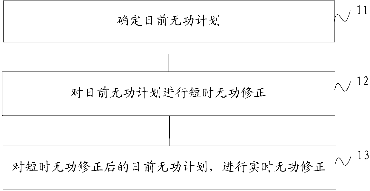
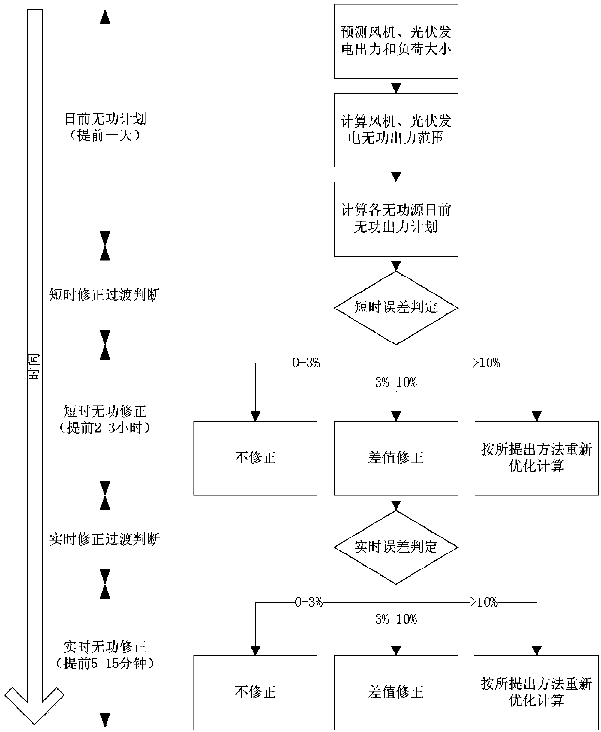
[0033] The embodiment of the present invention divides the grid reactive power scheduling into three time scales. First of all, the 24-hour output value of each generator on the second day is determined and reported at 17:00 the day before, that is, the output plan for the day before. In the previous plan, it is necessary to predict the wind speed and light intensity, and obtain the active power output value, and then calculate the reactive power scheduling range. After the day-ahead reactive power plan is determined, short-term reactive power correction is performed 2-3 hours before the scheduling instruction is executed. In the case of serious deviation between the original planned value and the actual operating value, the re-prediction and the adjustment of the reactive power output plan at this moment and the rest of the day are completed in time. Finally, real-time reactive power correction is performed 5-15 minutes before the scheduling instruction is executed to eliminate sudden uncertainties.
[0034] like figure 1 As shown, an embodiment of the present invention provides a flowchart of a method for coordinating and controlling reactive power of a power grid, including:
[0035] 11. Determine the current reactive power plan;
[0036] 12. Short-term reactive power correction for the previous reactive power plan;
[0037] 13. Perform real-time reactive power correction for the day-ahead reactive power plan after short-term reactive power correction.
[0038] Optionally, the determining the day-ahead reactive power plan includes: predicting the wind speed, light intensity and load size to obtain a prediction result; and calculating the wind and light day-ahead reactive power plan according to the prediction result.
[0039] Specifically, the reactive power plan has sufficient time for dynamic reactive power optimization calculation, but the prediction accuracy of distributed power output and load size is not high, so the reactive power control at this time scale aims to maximize the voltage stability margin. The hour-level optimization method is adopted in the time dimension, that is, an optimal reactive power output value is calculated for each hour of the next day. The optimization variables involved in regulation include wind turbines, photovoltaic generators, micro-turbines, on-load taps and capacitors. For the limitation of the switching times of on-load taps and capacitors, the following methods are used to solve the problem: first carry out 24h static optimization, obtain the difference between the switching values of two adjacent time periods and sort them, and formulate the pre-action according to the difference. table, and dynamically revise this table according to time advancement. This method can take into account the correlation between the action of the voltage regulating tap and the capacitor.
[0040] Aiming at the prediction of the output and load of the distributed power source on the day-ahead time scale, the present invention adopts the prediction method of Markov. Taking wind speed prediction as an example, the specific steps are as follows:
[0041] (1) Assume that the minimum wind speed in the historical data is v min , the maximum wind speed v max , the discretization step size of wind speed is taken as (v max -v min )/n, from v min to v max Divide the wind speed into n segments.
[0042] (2) Set one hour as a time period. According to the historical data, the state transition probability matrix between each time period is established:
[0043]
[0044] s ij = H ij Σ j = 1 n H ij
[0045] In the formula: t=0,1,2,…,24; S t is the state transition probability matrix from the (t-1)th hour to the tth hour, in particular, S 0 is the state transition probability matrix from 24:00 on the previous day to 0:00 on the forecast day; s ij is the state transition probability of the wind speed from the (t-1) hour segment i to the t hour segment j; H ij is the number of changes in the wind speed from the (t-1) hour segment i to the t hour segment j.
[0046] (3) Given the initial wind speed value v int , assuming v int In the wind speed section k, then in S 0 find element s in row k k1 ,s k2 …s kn , these elements establish the probability vector of wind speed distribution at the initial moment:
[0047] P 1 =(p(1),p(2),...,p(n))
[0048] In the formula: p(1), p(2),...,p(n) are the probabilities of wind speed in each section, and their values correspond to s k1 ,s k2 ,…,s kn.
[0049] (4) Calculate the probability vector of wind speed distribution for each hour:
[0050] P t+1 =P t S t
[0051] Further, the probability space of wind speed distribution for each hour is obtained:
[0052] W t ={p(i),v(i); i=1,2,...,n}
[0053] In the formula: W t is the probability space of wind speed distribution in the t-th hour, p(i) is the probability of the wind speed in the i-th segment, and v(i) is the mean value of the wind speed in the i-th segment.
[0054] (5) According to the relationship between wind speed and fan output:
[0055] P = 0 , v ≤ v ci a + bv , v ci ≤ v ≤ v r P r , v r v ≤ v co 0 , v v co
[0056] Calculate the fan output value corresponding to each wind speed segment, and segment the fan output. At this time, some wind speed segments may correspond to the same fan output value, then these segments are merged, and their corresponding wind speed distribution probabilities are added to obtain the combined fan output distribution probability. Let the final fan output segment number be n w , the probability space of fan output distribution in each hour is obtained as:
[0057] D t ={p w (i),P w (i); i=1,2,...,n w}
[0058] where: v ci is the cut-in wind speed; v i is the rated wind speed; v co is the cut-out wind speed; p r is the rated output power of the wind turbine; and a=P r v ci /(v ci -v r ) and b=P r /(v r -v ci ) are constant coefficients. D t is the probability space of fan output distribution in the t-th hour; p c (i) is the output probability of the fan in the i-th stage; P w (i) is the fan output value of the i-th stage.
[0059] After the fan output value is obtained by prediction, the reactive power output range is obtained.
[0060] Q max wind = S 2 - P wind 2
[0061] where P wind Injecting power into the active power of wind power generation, which is affected by natural resources; S is the rated capacity of the wind turbine; It is the maximum reactive power output of the fan.
[0062] The dynamic reactive power optimization model is a multi-variable and multi-constraint mixed integer nonlinear optimization problem with both continuous control variables and discrete control variables. For such problems, genetic algorithms and interior point methods are commonly used. The algorithm is good at dealing with discrete variables and the interior point method is good at dealing with continuous variables. The present invention proposes to use a hybrid algorithm combining genetic algorithm and interior point method to solve, and divides reactive power optimization into two sub-optimization models of discrete variables and continuous variables. The algorithm deals with discrete variables in reactive power optimization and the interior point method deals with continuous variables. This hybrid algorithm combines the advantages of genetic algorithm and interior point algorithm to avoid its shortcomings and effectively improve the solution efficiency.
[0063] In the daily reactive power plan solution algorithm, the objective function is to maximize the voltage stability margin, and the optimization variables include wind turbines, photovoltaic generators, micro-turbines, on-load taps and capacitors. The optimization method adopts the hybrid algorithm proposed by the present invention to solve. The basic idea of the hybrid algorithm is: first, without considering the discrete constraints of discrete variables, the nonlinear interior point algorithm is used to solve the initial solution, and then the discrete optimization problem and the continuous optimization problem are iteratively solved.
[0064] In the discrete optimization problem, the continuous variables are set to be constant, and only the discrete variables are encoded and cross-mutated to obtain the continuous variables of each time period. In the continuous optimization problem, the discrete variables are set to be constant, and the interior point algorithm is used. Perform optimization calculation on continuous variables to obtain discrete variable values, and repeat the cross iteration until the convergence conditions are met, and then the final optimization results including continuous variables and discrete variables can be obtained. The specific steps of the hybrid algorithm are as follows:
[0065] (1) Divide the control variables into continuous variables and discrete variables, relax the constraints of discrete variables, and use the nonlinear interior point method for optimization calculation to obtain the initial solution in are the initial solution of the fan output, the initial solution of the photovoltaic output, the initial solution of the micro gas turbine output and the initial solution of the capacitor output;
[0066] (2) Set the number of iterations to k=1;
[0067] (3) keep unchanged, with Using genetic algorithm to solve the discrete optimization subproblem for the control variables, we get
[0068] (4) Order Keep constant, the nonlinear interior point method is used to solve the continuous optimization sub-problem, and we get Check whether the convergence condition is satisfied, if not, k=k+1, turn to step (3), if satisfied, the calculation is over, and the optimization result is obtained.
[0069] Optionally, the performing short-time reactive power correction on the day-ahead reactive power plan includes: determining a short-time correction method, and performing short-time reactive power output correction according to the determined short-time correction method.
[0070] Specifically, based on the short-term distributed power output and load prediction, the time dimension is 30 minutes. The short-term rolling planning link needs to monitor the implementation of the previous reactive power plan. In the case of serious deviation between the original plan and the actual load, the re-prediction of the remaining period of the day and the adjustment of the reactive power output plan should be completed in time, that is, rolling correction of each distribution The reactive power output plan of the type power supply in the remaining period. Since the short-term time scale has greatly improved the output and load prediction accuracy of distributed power generation compared with the previous days, and there is sufficient reactive power adjustment time and margin, the optimization goal is to minimize the risk, that is, the minimum probability of voltage overrun. Potential risks to the system are kept as low as possible on short time scales.
[0071] Since the adjustment of the on-load voltage regulating tap will affect multiple 10kV lines of the same bus, this optimization variable is not considered in the short-term reactive power correction.
[0072] For the distributed power and load forecasting on the short-term time scale, the present invention adopts the Auto-Regressive and Moving Average Model (ARMA). Taking wind speed prediction as an example, the specific steps are as follows:
[0073] (1) Read in the historical wind speed data, standardize the data, and obtain a time series that is stable, normal, and zero mean.
[0074] (2) Set the initial value of the autoregressive and moving average model order.
[0075] (3) Estimate AR model parameters.
[0076] (4) Calculate the residual sequence and residual variance.
[0077] (5) Calculate the criterion function value BIC.
[0078] (6) If the model order does not reach the upper limit, go to step (3); otherwise, stop the iteration, and take the p corresponding to the smallest BIC value as the final order of the AR model.
[0079] (7) Fit the ARMA model, calculate the model parameters and carry out the adaptability test.
[0080] (8) Model the wind speed and obtain the predicted wind speed sequence.
[0081] Through the wind and light prediction of short-term reactive power correction, the active power output value is obtained, and then the reactive power output range is obtained. The method is the same as the previous reactive power plan. In the short-time reactive power correction solution algorithm, the objective function is taken as the minimum probability of voltage exceeding the limit. The optimization method is the same as the hybrid algorithm of the day-ahead reactive power plan. The probability of voltage over-limit is calculated by random power flow based on semi-invariant. Specific steps are as follows.
[0082] Linearizing the power system node injection equation and branch power flow equation, and first-order Taylor expansion at the reference operating point, we can get
[0083] S 0 + ΔS = f ( X 0 + ΔX ) = f ( X 0 ) + J 0 ΔX + . . . . . Z 0 + ΔZ = g ( X 0 + ΔX ) = g ( X 0 ) + G 0 ΔX + . . . .
[0084] In the formula: S 0 , X 0 ,Z 0 ΔS, ΔX, ΔZ are random disturbances, respectively.
[0085] It is assumed that the random changes of the load, wind speed and light intensity of each node are independent of each other, the wind speed in each period obeys the Weibull distribution, and the light intensity obeys the beta distribution. Using the properties of semi-invariants, the convolution operation is simplified to several semi-invariant algebraic operations, and after obtaining the semi-invariants of each order of the quantity to be calculated, the probability density function of the state variables is calculated by the Gram-Charlier series expansion method. .
[0086] Optionally, performing real-time reactive power correction on the day-ahead reactive power plan after short-term reactive power correction includes: determining a real-time correction method, and performing real-time reactive power output correction according to the determined real-time correction method.
[0087] Real-time reactive power correction is a further adjustment and correction of short-term correction, and generally the adjustment amount is small. A 10-minute-level approach is used in the time dimension. Due to the short time, the optimization variables involved in regulation are mainly micro gas turbines. The stable power supply is used as a buffer unit to eliminate uncertain factors and achieve the purpose of the highest economy. Therefore, the optimization goal is to minimize the network loss. The prediction method of distributed power output and load is the same as the short-term reactive power correction ARMA model. Due to the short time, in order to eliminate the possible uncertainty, the solution method adopts the interior point method with stable output results.
[0088] In the short-term reactive power correction, the predicted value of the distributed power output and load in the previous reactive power plan is first compared with the actual value, and the error between the predicted value and the actual value is judged. If the error is less than 3%, it is considered that the previous reactive power plan is reasonable and does not need to be adjusted; if the error is greater than 3% and less than 10%, it is considered that the previous reactive power plan has a small deviation from the actual. Correct the difference for the remaining period. Find a nearby reactive power source for the load point with a large difference between reactive power supply and demand, and adjust the reactive power output plan of the reactive power source according to the difference; if the error is greater than 10%, it is considered that the previous reactive power plan has a large deviation from the actual. Re-optimize the calculation for the remaining period. The real-time reactive power correction transition method is the same as above.
[0089] figure 2 This is a flowchart of another grid reactive power coordination control method provided by an embodiment of the present invention.
[0090] The embodiment of the present invention determines the day-ahead reactive power plan, performs short-time reactive power correction on the day-ahead reactive power plan, and performs real-time reactive power correction on the day-ahead reactive power plan after the short-time reactive power correction. Thus, multi-time scale reactive rolling correction is realized.
[0091] In the embodiment of the present invention, the variation trend of distributed generation and load at different time scales is analyzed, and a reactive power and voltage optimization plan and strategy of sequential progressive rolling is developed. Research on forecasting methods suitable for distributed generation output and load changes at different time scales. According to different scheduling ideas and goals at different time scales, mathematical models are established, and suitable algorithms are used to solve different mathematical models. Based on the error analysis, the transition connection method between different time scales is considered, which reduces the repeated calculation while ensuring the accuracy and reliability of the optimal scheduling.
[0092] like image 3 As shown, an embodiment of the present invention provides a power grid reactive power coordination control device, including:
[0093] The first module 31 is used to determine the reactive power plan for the day before;
[0094] The second module 32 is used to perform short-term reactive power correction on the previous reactive power plan;
[0095] The third module 33 is used to perform real-time reactive power correction on the day-ahead reactive power plan after short-term reactive power correction.
[0096] Optionally, the first module is specifically used for predicting wind speed, light intensity and load size to obtain a prediction result; according to the prediction result, calculate the wind and light day-ahead reactive power plan.
[0097] Optionally, the second module is specifically configured to determine a short-term correction method, and perform short-term reactive power output correction according to the determined short-term correction method.
[0098] Optionally, the third module is specifically configured to determine a real-time correction method, and perform real-time reactive power output correction according to the determined real-time correction method.
[0099] The embodiment of the present invention determines the day-ahead reactive power plan, performs short-time reactive power correction on the day-ahead reactive power plan, and performs real-time reactive power correction on the day-ahead reactive power plan after the short-time reactive power correction. Thus, multi-time scale reactive rolling correction is realized.
[0100] Various modifications and variations can be made in the present invention by those skilled in the art without departing from the spirit and scope of the invention. Thus, provided that these modifications and variations of the present invention fall within the scope of the claims of the present invention and their equivalents, the present invention is also intended to include these modifications and variations.
PUM


Description & Claims & Application Information
We can also present the details of the Description, Claims and Application information to help users get a comprehensive understanding of the technical details of the patent, such as background art, summary of invention, brief description of drawings, description of embodiments, and other original content. On the other hand, users can also determine the specific scope of protection of the technology through the list of claims; as well as understand the changes in the life cycle of the technology with the presentation of the patent timeline. Login to view more.