
Light fixtures and lighting fixtures

A technology for information circuits and frames, which is applied to lighting devices, components of lighting devices, and damage prevention measures for lighting devices. It can solve problems such as long wiring distances, miswiring, and complicated wiring structures. Achieve the effect of simplifying the wiring structure

Active Publication Date: 2017-05-03
TOSHIBA LIGHTING & TECH CORP
View PDF5 Cites 0 Cited by
  • Summary
  • Abstract
  • Description
  • Claims
  • Application Information

AI Technical Summary

Problems solved by technology

[0006] However, when the lamp device has a plurality of pins for power supply or signal use, the wiring distance for connecting the pins to the corresponding connection parts becomes longer, or the wiring crosses, etc., and the wiring structure becomes complicated. Miswiring may occur

Method used


Image

  • Light fixtures and lighting fixtures
  • Light fixtures and lighting fixtures
  • Light fixtures and lighting fixtures

Examples


Embodiment Construction

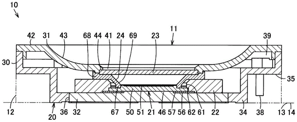
[0036] Below, refer to Figure 1 to Figure 7 The first embodiment will be described.

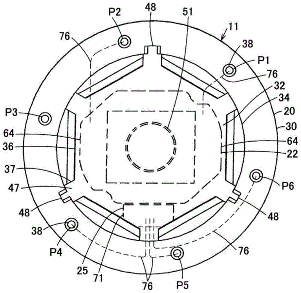
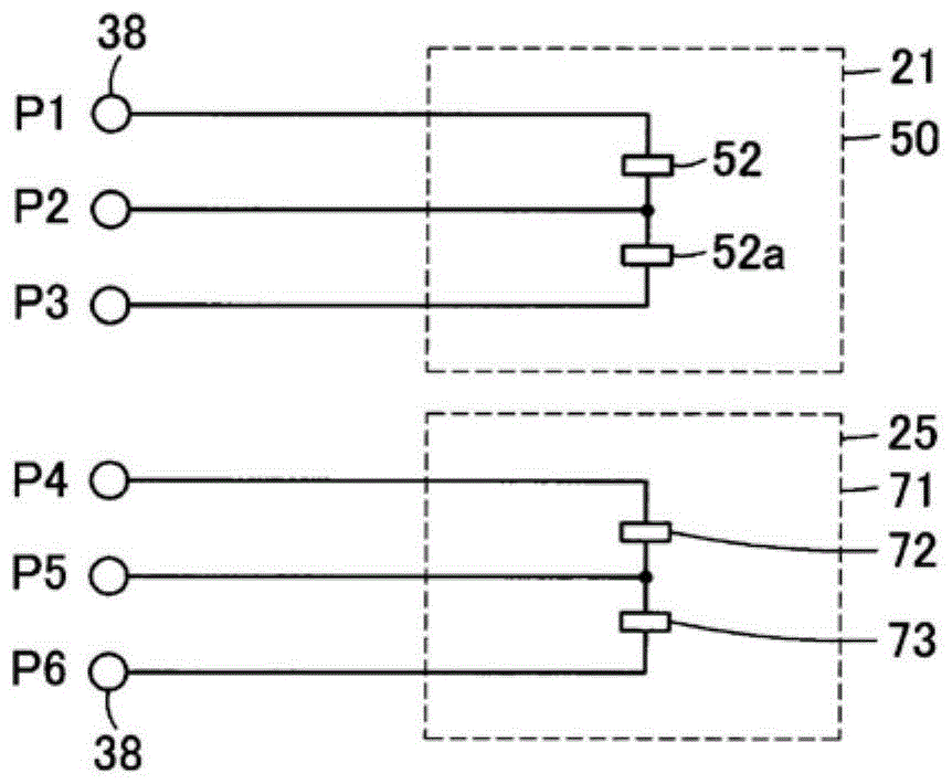
[0037] Such as image 3 and Figure 7 As shown, the lighting device 10 includes: a lamp device 11, a lamp holder 12 detachably mounted on the lamp device 11, an appliance main body 14 having a radiator 13 thermally connected to the lamp device 11 mounted on the lamp holder 12, And a lighting device (not shown) that is disposed on the device main body 14 and the like and is electrically connected to the lamp device 11 through the lamp socket 12 . The lighting device is configured to convert commercial AC power into predetermined DC power to supply power to the lamp device 11 , and to control the lamp device 11 by inputting an information signal output from the lamp device 11 . In addition, in the drawings, the light emitting direction of the lamp device 11 is set upward for illustration, but when the lighting device 10 is, for example, a downlight, etc., the light emitting direction of the...


PUM


Abstract

The present invention provides a lamp device and a lighting device capable of simplifying the wiring structure. A protruding portion (34) having a heat dissipation portion (32) protrudes from a rear central portion of the frame body (20) on the light emitting side, that is, on the opposite side to the front side. The light emitting module (21) has a substrate (50) and a light emitting part (51) formed on the front surface of the substrate, the light emitting part is arranged in the center of the frame body (20), and the rear surface of the substrate and the heat dissipation part thermal connection on the front side. A pair of power supply parts (64) for supplying power to the light emitting module are arranged around the light emitting part in the frame body (20). The information circuit (25) is arranged in the frame body (20) around the light emitting part and at a position different from the pair of power supply parts, and outputs information to the outside. A plurality of pins (38) are arranged around the protruding portion at intervals along the rear peripheral portion of the frame. A connection mechanism (76) connects each power supply unit to a pin located near each power supply unit, and connects an information circuit to a pin located near the information circuit.

Description

technical field [0001] The present invention relates to a lamp device using a light emitting module and a lighting device using the lamp device. Background technique [0002] Conventionally, in a lamp device using a light-emitting module, a light-transmitting member is arranged on the front side of the housing on the light-emitting side, and a protruding portion having a heat dissipation portion is protruded on the opposite rear side. In addition, in the housing, the light-emitting module is disposed on the front side of the heat dissipation part, and the reflector and the lighting circuit are further disposed on the front side of the light-emitting module. [0003] Around the protruding portion, a plurality of pins protrude from the rear peripheral portion of the frame. The pins include two pins for AC power supply, two pins for dimming signal input, and one pin for grounding, and these pins are connected to the lighting circuit. [0004] patent documents [0005] Patent...

Claims


Application Information

Patent Timeline
Patent Type & Authority Patents(China)
IPC IPC(8): F21S2/00F21V23/04F21V23/00
CPCF21V15/01F21V19/003F21V23/002F21V23/006F21K9/20F21V29/71F21V29/507
Inventor 木宫淳一石田正纯大塚诚
Owner TOSHIBA LIGHTING & TECH CORP
Features
  • Generate Ideas
  • Intellectual Property
  • Life Sciences
  • Materials
  • Tech Scout
  • Unparalleled Data Quality
  • Higher Quality Content
  • 60% Fewer Hallucinations
Learn More