Vehicular sensor device and vehicular stabilizing system using vehicular sensor device
A technology for sensor devices and stabilization systems, applied to vehicle components, steering control installed on vehicles, transportation and packaging, etc., can solve problems such as difficult installation, high cost of sensor devices, and difficulty in installing sensors
- Summary
- Abstract
- Description
- Claims
- Application Information
AI Technical Summary
Problems solved by technology
Method used
Image

Examples
no. 1 approach
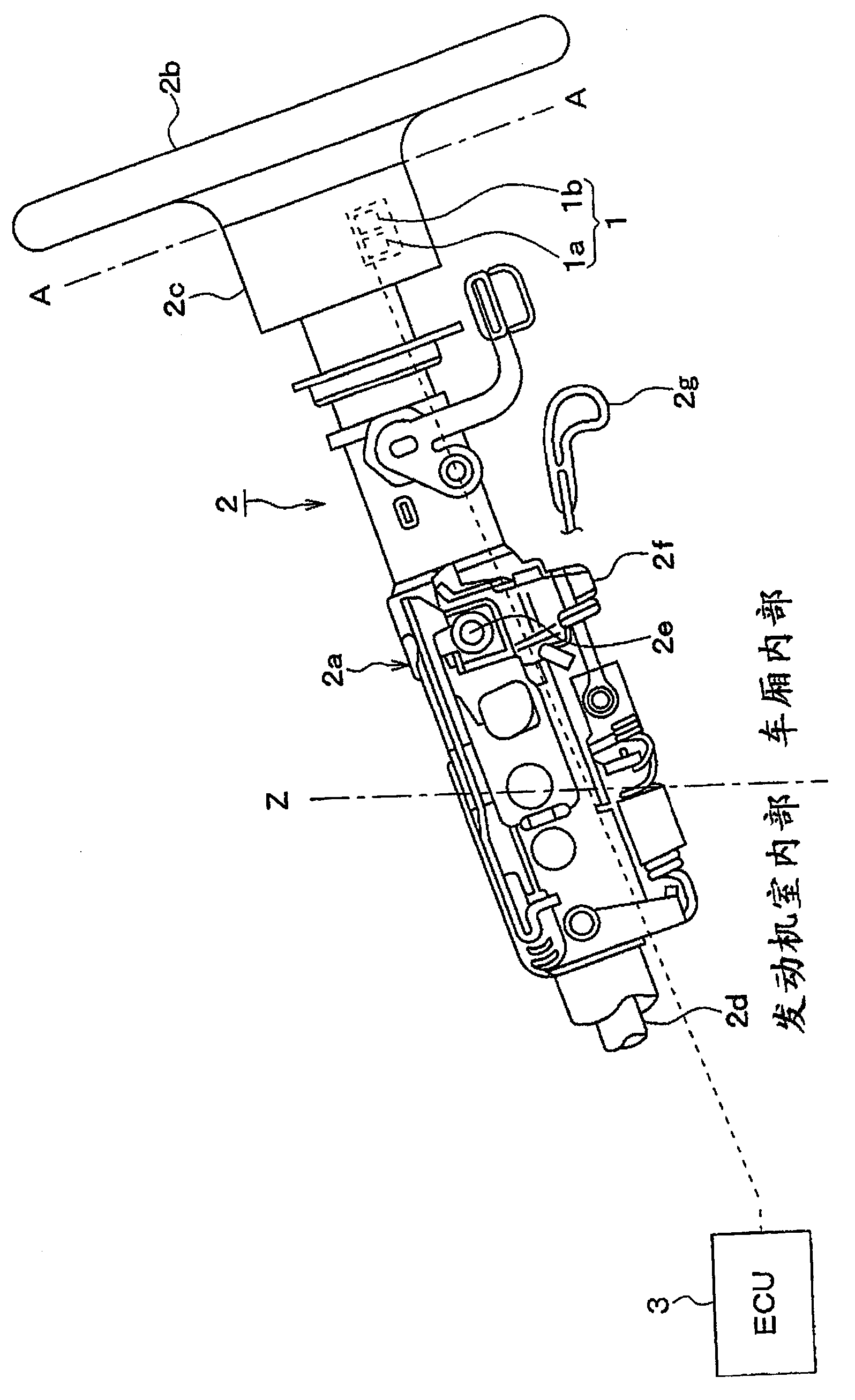
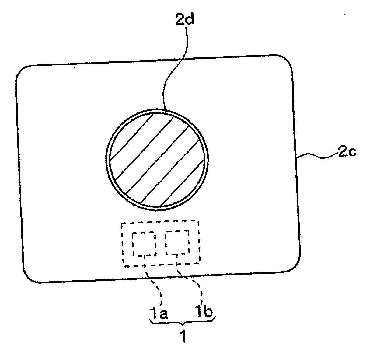
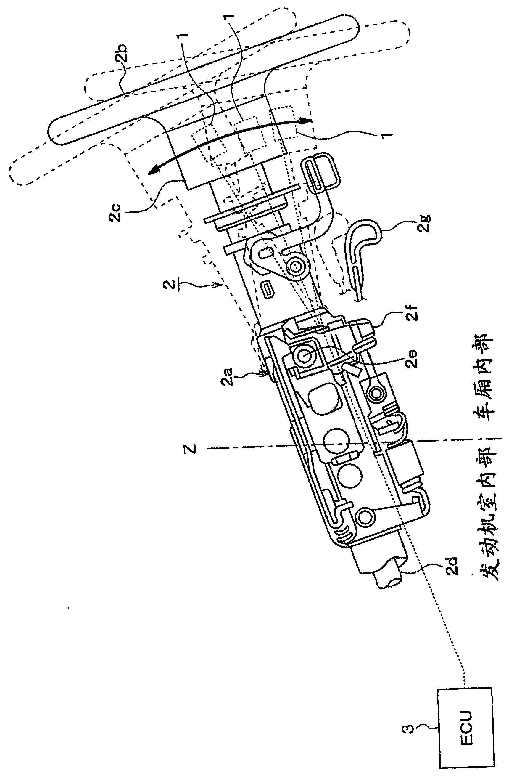
[0032] Hereinafter, a first embodiment of the present invention will be described. figure 1The steering mechanism 2 mounted with the vehicle sensor device 1 according to this embodiment is shown, and the ECU 3 in the ESC system into which the detection signal from the vehicle sensor device 1 is input is also shown. figure 2 is along figure 1 Schematic representation of the cross-section of midline A-A. Hereinafter, the arrangement structure of the vehicle sensor device 1 will be described with reference to these drawings.
[0033] The vehicle sensor device 1 according to this embodiment includes a vehicle motion amount sensor 1a and a steering angle sensor 1b. The vehicle motion amount sensor 1a includes driving dynamics sensors such as a front-rear acceleration sensor for detecting acceleration Gx in the vehicle front-rear direction, a lateral acceleration sensor for detecting acceleration Gy in the vehicle lateral direction, and a rotation angle sensor for detecting a rot...
no. 2 approach
[0072] Hereinafter, a second embodiment of the present invention will be described. In the first embodiment described above, the vehicle sensor device 1 is mounted to the combination switch device 2c. In the present embodiment, the vehicle sensor device 1 is mounted to a position different from that of the first embodiment.
[0073] Figure 8 It is a schematic diagram showing the power steering device in which the vehicle sensor device 1 is mounted in the present embodiment. Figure 9 yes Figure 8 A cross-sectional view of a part of a rack in a power steering apparatus shown in , where the vehicle sensor device 1 is attached to the rack.
[0074] Figure 8 The illustrated power steering device 11 is of a rack assist type, and includes a rack assist mechanism 12 that assists forward and backward movement of the rack by means of rotation of a motor.
[0075] The rack assist mechanism 12 includes a ball screw 13 , an assist motor 14 and a rack shaft 15 . When the pinion sh...
Embodiment approach
[0082] In the above embodiments, the vehicle sensor device 1 is located inside or near the tilt mechanism 2a, so that the influence of the tilt angle θ on the vehicle motion sensor 1a can be eliminated. However, the vehicle motion amount sensor 1a may be provided in such a manner that the vehicle motion amount sensor 1a is not affected by the inclination angle.
[0083] For example, the vehicle motion amount sensor 1a may be positioned on a portion where the tilt angle θ of the tilt mechanism 2a does not change due to tilt adjustment, instead of a portion where the tilt angle θ of the tilt mechanism 2a changes due to tilt adjustment (steering side ). In this case, the vehicle motion sensor 1a still needs to be located in the vehicle compartment to reduce the influence of heat and vibration in the engine room on the vehicle motion sensor 1a, thereby simplifying the structure of the electrical wiring and facilitating the installation of the electrical wiring.
[0084] Such as ...
PUM
 Abstract
Description
Claims
Application Information