

Flue sheet structure for tunnel exhaust duct
A technology of exhaust duct and flue plate, which is applied in mine/tunnel ventilation, mining equipment, earth square drilling, etc., to achieve the effect of reducing long-term deflection and satisfying surface roughness
- Summary
- Abstract
- Description
- Claims
- Application Information
AI Technical Summary
Problems solved by technology
Method used
Image

Examples
Embodiment Construction
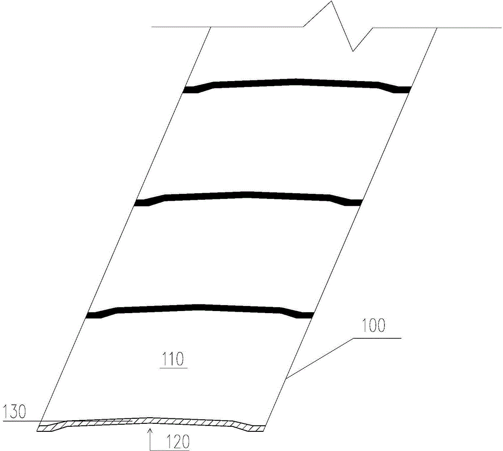
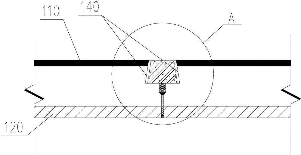
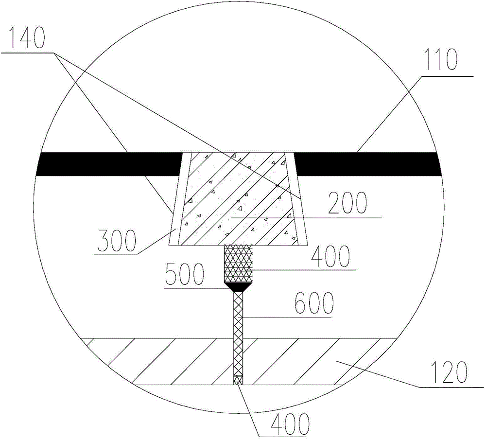
[0024] Such as figure 1 As shown, the flue panel structure for a tunnel exhaust duct in this embodiment includes several prefabricated flue panels 100, and the prefabricated flue panels 100 are sequentially spliced along the length direction of the tunnel. The cross section of the prefabricated flue panels 100 is Arched, the prefabricated flue panel has a raised top surface 110, a concave bottom surface 120 and two butt end surfaces 130, the two butt end surfaces 130 are set to the back, and the convex top surface 110 and the concave bottom surface 120 are arranged between the two butt end surfaces 130 , the convex top surface 110 is above the concave bottom surface 120 . Such as figure 2 and image 3 As shown, there are elongated notches 140 formed at the joints between the two butt end surfaces 130 and the raised top surface 110, and the adjacent prefabricated flue panels are butted through the butt end surfaces 130 and the notches 140, and the notches 140 are filled wi...
PUM
 Abstract
Description
Claims
Application Information