Clock component for receiving an organ by insertion

A technology for accommodating components and accommodating structures, applied in mechanically driven clocks, clocks, clock driving mechanisms, etc., can solve problems such as shortage and space occupation

Inactive Publication Date: 2014-10-29
ROLEX SA
View PDF4 Cites 3 Cited by
  • Summary
  • Abstract
  • Description
  • Claims
  • Application Information

AI Technical Summary

Problems solved by technology

However, the ability to find existing solutions that withstand expulsion is insufficient in some cases, for example, where an inserted gemstone is k

Method used


Image

  • Clock component for receiving an organ by insertion
  • Clock component for receiving an organ by insertion
  • Clock component for receiving an organ by insertion

Examples


Embodiment Construction

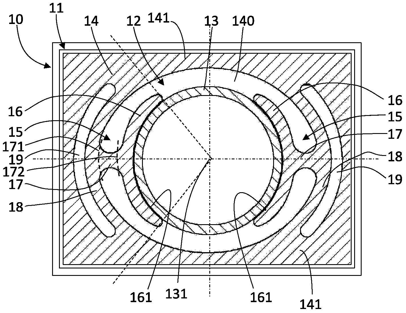
[0021] A first embodiment of a timer 10 according to the invention will be referred to in the appended figure 1 Described below. For example, the timer is a watch, such as a watch.

[0022] The timepiece includes a timepiece movement 11 . The movement comprises an assembly 12 comprising a member 13 mounted in a timepiece part 14 , in particular driven into the timepiece part 14 .

[0023] Timepiece part 14 includes an opening 140 intended to receive member 13 by driving member 13 into it. The component comprises at least one housing structure 15 for housing a component, in this particular example two component housing structures 15 .

[0024] exist figure 1 In , the timepiece components as well as the components are shown in cross-section, in particular in sections on a plane perpendicular to the direction or axis 131 in which the components are driven into the components.

[0025] Each containment structure 15 includes:

[0026] - receiving element 16 for contacting the...


PUM


Abstract

A horology component (14) comprising an opening (140) intended to house a member (13) by the latter being driven into the opening, the component comprising at least one housing structure (15) for housing the member, each housing structure comprising: a housing element (16) intended to come into contact with the member, a connecting element (17), an elastically deformable element (18), the housing element being mounted on the elastically deformable element via the connecting element.

Description

technical field [0001] The invention relates to a timepiece component for receiving a driven-in component. The invention also relates to an assembly comprising such a component and components mounted or driven into the component. The invention also relates to a movement comprising such a part or such an assembly. The invention finally relates to a timepiece, in particular a watch, comprising such a movement or such an assembly or such a part. Background technique [0002] Driving an attached jewel into a component such as a semi-finished movement or lever cannot necessarily be easily done. Driving gemstones into semi-finished movements made of brass is a known and mastered operation, while using other materials, especially those with little or no plastic deformation domain, may will cause more problems. In this case, the use of elastic geometries is an attractive option, proving that such a structure provides the required rotational moment resistance and the required dri...

Claims


Application Information

Patent Timeline
IPC IPC(8): G04B1/00G04B33/00
CPCG04B13/022G04B17/325G04B37/0008G04B29/04G04B17/066G04B15/14G04B37/0091G04B31/04G04B13/02
Inventor 皮埃尔·卡蒂奥
Owner ROLEX SA
Why Eureka
Try Eureka