Hydraulic rotary weir gate

A rotary and weir gate technology, which is applied in barrage/weirs, water conservancy projects, sea area projects, etc., can solve the problems of ground landscape damage and increased weir gate installation space, etc.

Inactive Publication Date: 2014-11-05
WUHAN SHENGYU DRAINING SYST
View PDF6 Cites 28 Cited by
  • Summary
  • Abstract
  • Description
  • Claims
  • Application Information

AI Technical Summary

Problems solved by technology

[0003] The existing weir gate requires more installation space, and both underground and above-ground spaces have corresponding design requirements, which has caused damage to the ground landscape

Method used


Image

  • Hydraulic rotary weir gate
  • Hydraulic rotary weir gate

Examples


Embodiment Construction

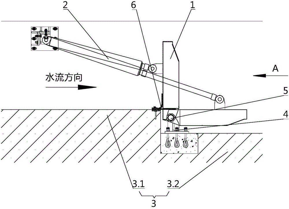
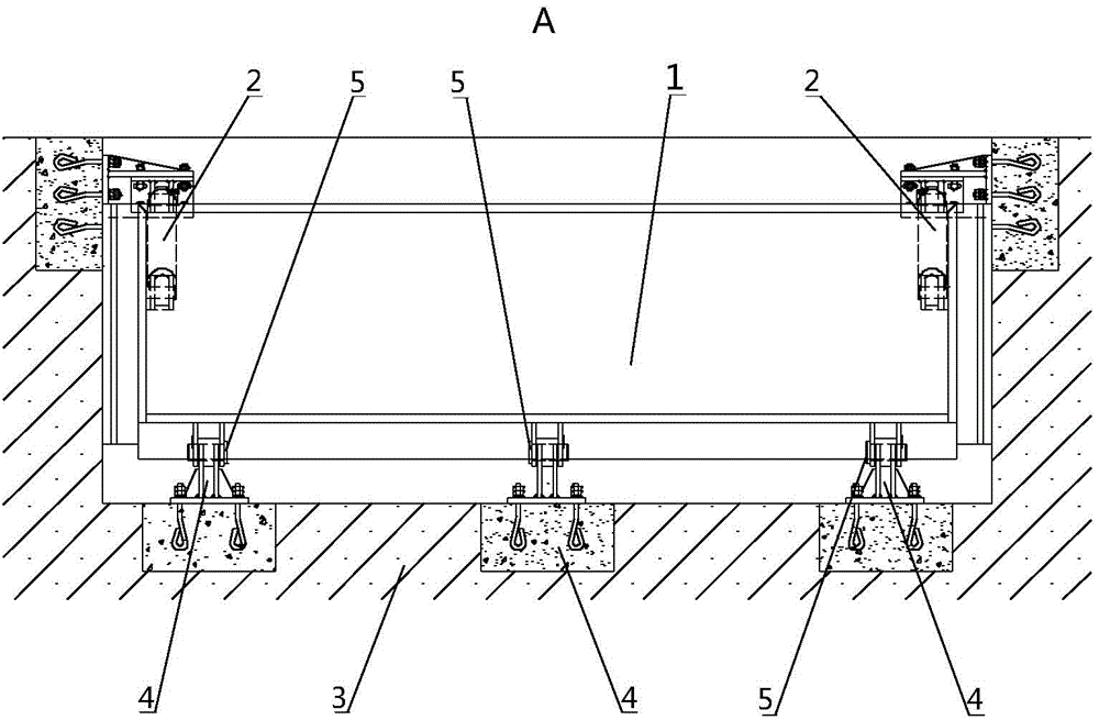
[0019] Such as figure 1 with figure 2 As shown, the hydraulic rotary weir gate designed by the present invention includes a door panel 1 and an oil cylinder 2; A mounting seat 4 is provided, and a rotating shaft 5 is provided on the mounting seat 4; the bottom of the door panel 1 is rotationally connected with the rotating shaft 5; the contact seal between the door panel 1 and the flow channel base 3 is provided.

[0020] Further, the bottom surface of the flow channel base 3 upstream of the door panel 1 is higher than the bottom surface of the flow channel base 3 on which the installation seat 4 is installed; in this way, the door panel can be placed in a horizontal position, so that the flow channel is fully opened.

[0021] Further, the bottom surface of the flow channel base 3 includes a high section 3.1 and a low section 3.2, and the high section 3.1 and the low section 3.2 have a stepped structure; Transition to paragraph 3.2.

[0022] Further, the rotation center of...


PUM


Abstract

The invention discloses a hydraulic rotary weir gate comprising a gate plate and oil cylinders. The fixed ends of the oil cylinders are fixed on a flow channel base, and the driving ends of the oil cylinders are hinged to the end faces of the gate plate. Mounting bases are arranged on the flow passage base, and a rotating shaft is arranged on each mounting base. The bottom of the gate plate is rotationally connected with the rotating shafts. Two sides of the gate plate and the side walls of the flow channel base are in contact seal. Whether underground mounting space or overground mounting space of the hydraulic rotary weir gate is much smaller than that of an existing weir gate, and meanwhile the oil cylinders can be mounted under the ground without affecting ground landscape; the gate sheet can be stopped at different angular positions so as to control different water distribution flows or regulate different headwater levels.

Description

technical field [0001] The invention relates to the technical field of water supply and drainage equipment, in particular to a hydraulic rotary weir gate. Background technique [0002] In my country's urban water supply and drainage projects, water supply devices and drainage devices often have a clear division of labor, and each uses its own field. As the construction of water supply and drainage systems in cities in our country is becoming more and more perfect, the demand for devices that can be used for both water supply projects (water distribution) and drainage projects (adjustment of upstream water level) is also increasing. Therefore, there is an urgent need for a weir gate technology that can be used not only in water supply projects but also in drainage projects. [0003] The existing weir gate requires an increased installation space, and both underground and above-ground spaces have corresponding design requirements, which has caused damage to the ground landsca...

Claims


Application Information

Patent Timeline
Patent Type & Authority Applications(China)
IPC IPC(8): E02B7/40E02B7/54
Inventor 周超
Owner WUHAN SHENGYU DRAINING SYST
Why Eureka
Try Eureka