High-altitude propeller and propeller tip winglet capable of improving efficiency of high-altitude propeller

A technology of efficiency and blades, applied in propellers, aircraft parts, transportation and packaging, etc., can solve the problems of increasing propeller energy loss, reducing the effective angle of attack of each blade position, and reducing propeller efficiency

Active Publication Date: 2014-11-12
NORTHWESTERN POLYTECHNICAL UNIV
View PDF7 Cites 19 Cited by
  • Summary
  • Abstract
  • Description
  • Claims
  • Application Information

AI Technical Summary

Problems solved by technology

[0003] For conventional layout propellers, blade diameter has the greatest impact on aerodynamic efficiency, and propeller efficiency can be improved by increasing the diameter of the high-altitude propeller, but considering the overall size requirements of the high-altitude aircraft and the structural performance of the blade, the blade diameter is limited
For large-diameter high-altitude propellers, during the blade rotation process, the blade tip is in the high-speed airflow, and the airflow in the high-pressure area on the lower surface of the blade will bypass the blade tip and flow to the upper surface of the blade. The three-dimensional effect is serious, and the induced vortex of the blade tip is strengthened. The energy loss of the propeller is exacerbated, and at the same time, the effective angle of attack of each position of the blade is reduced, which reduces the efficiency of the propeller

Method used


Image

  • High-altitude propeller and propeller tip winglet capable of improving efficiency of high-altitude propeller
  • High-altitude propeller and propeller tip winglet capable of improving efficiency of high-altitude propeller
  • High-altitude propeller and propeller tip winglet capable of improving efficiency of high-altitude propeller

Examples


Embodiment Construction

[0030] The present invention is described in detail below in conjunction with accompanying drawing:

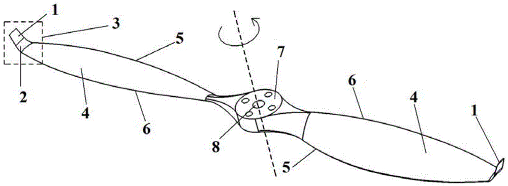
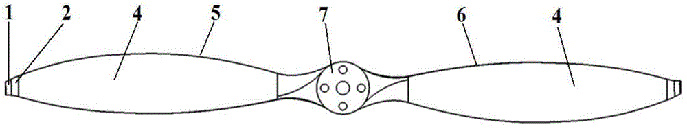
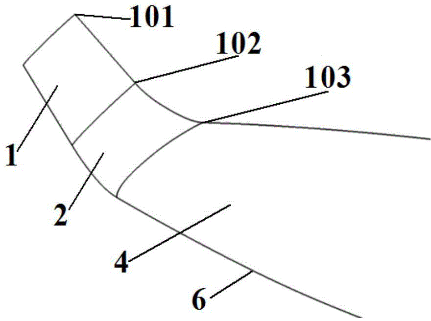
[0031] The present invention provides a blade tip winglet and a high-altitude propeller with improved high-altitude propeller efficiency, wherein the high-altitude propeller is a propeller suitable for a working height of 15-20 km, such as figure 1 with figure 2 As shown, the high-altitude paddle is made up of three parts, the paddle hub 7, the basic blade and the paddle-tip winglet. Wherein, 4 represents the upper surface of the basic blade, 5 represents the trailing edge of the basic blade, 6 represents the leading edge of the basic blade, and 9 represents the lower surface of the basic blade. The propeller hub 7 is provided with a propeller mounting hole 8 . The paddle-tip winglet is in the form of an upturned winglet, which is composed of a winglet straight plate section 1 and a winglet transition section 2 .

[0032] Since the geometric structure parameters of the pad...


PUM


Abstract

The invention discloses a high-altitude propeller and a propeller tip winglet capable of improving efficiency of the high-altitude propeller. The propeller tip winglet is of an upswept winglet form and comprises a winglet straight plate section and a winglet transition section, wherein the height of the propeller tip winglet is 3%-4% of the length of half propeller diameter of a base propeller; the height of the winglet straight plate section is 2%-3% of the half propeller diameter of the base propeller; the length of an end side stance wing-shaped chord of the propeller tip winglet is 60%-65% of the length of a propeller tip stance wing-shaped chord of the base propeller; the length of an intersection stance wing-shaped chord is 73%-78% of the length of a propeller tip stance wing-shaped chord of the base propeller; a torsion angle of the winglet straight plate section is 3-5 degrees smaller than a propeller tip stance wing-shaped torsion angle of the base propeller; a front edge sweepback angle of the propeller tip winglet is 10-15 degrees smaller than that of the propeller tip of the base propeller; an inclination angle of the propeller tip winglet is 35-45 degrees. The propeller tip winglet is capable of effectively reducing the strength of the inductive vortex of the propeller tip, reducing the energy dissipation of a screw propeller and finally effectively improving the working efficiency of a high-altitude propeller propelling system.

Description

technical field [0001] The invention belongs to the technical field of propeller design, and in particular relates to a blade tip winglet and a high-altitude propeller capable of improving the efficiency of the high-altitude propeller. Background technique [0002] The high-altitude aircraft uses electric energy converted from solar energy as the main energy source. The design goal is to hover at a fixed point for a long time or maneuver at a low speed within an altitude of about 20km. The "Helios" series of high-altitude and long-endurance UAVs all use propellers as propulsion devices. As the flight altitude increases, the Reynolds number decreases significantly, that is, the high-altitude propeller is in a low Reynolds number working state, and the propeller efficiency will be significantly reduced. Therefore, improving the aerodynamic efficiency of the high-altitude propeller is of great significance for high-altitude aircraft. [0003] For conventional layout propellers...

Claims


Application Information

Patent Timeline
Patent Type & Authority Applications(China)
IPC IPC(8): B64C11/20
Inventor 杨旭东张顺磊许建华朱敏宋超宋文萍宋笔锋安伟刚王海峰李育斌张玉刚
Owner NORTHWESTERN POLYTECHNICAL UNIV
Why Eureka
Try Eureka