Electronic component mounting device and electronic component mounting method

A technology for electronic component installation and electronic components, applied in the direction of electrical components, electrical components, etc., can solve problems such as difficulty in ensuring component supply, sprocket position maintenance, and inability to guarantee the stop position accuracy of the carrier tape, etc., to achieve the effect of ensuring the stop position accuracy

Active Publication Date: 2018-07-17
PANASONIC INTELLECTUAL PROPERTY MANAGEMENT CO LTD
View PDF4 Cites 0 Cited by
  • Summary
  • Abstract
  • Description
  • Claims
  • Application Information

AI Technical Summary

Problems solved by technology

[0008] However, when the power saving mode is applied, the power supply to the motor is cut off, so the position of the sprockets cannot be maintained against external forces that cause disturbance of the stop position of the carrier tape, such as when the top tape is peeled off.
In this way, there is a problem in the conventional technology that the stop position accuracy of the carrier tape cannot be guaranteed to achieve power saving, and it is difficult to ensure stable component supply.

Method used


Image

  • Electronic component mounting device and electronic component mounting method
  • Electronic component mounting device and electronic component mounting method
  • Electronic component mounting device and electronic component mounting method

Examples


Embodiment Construction

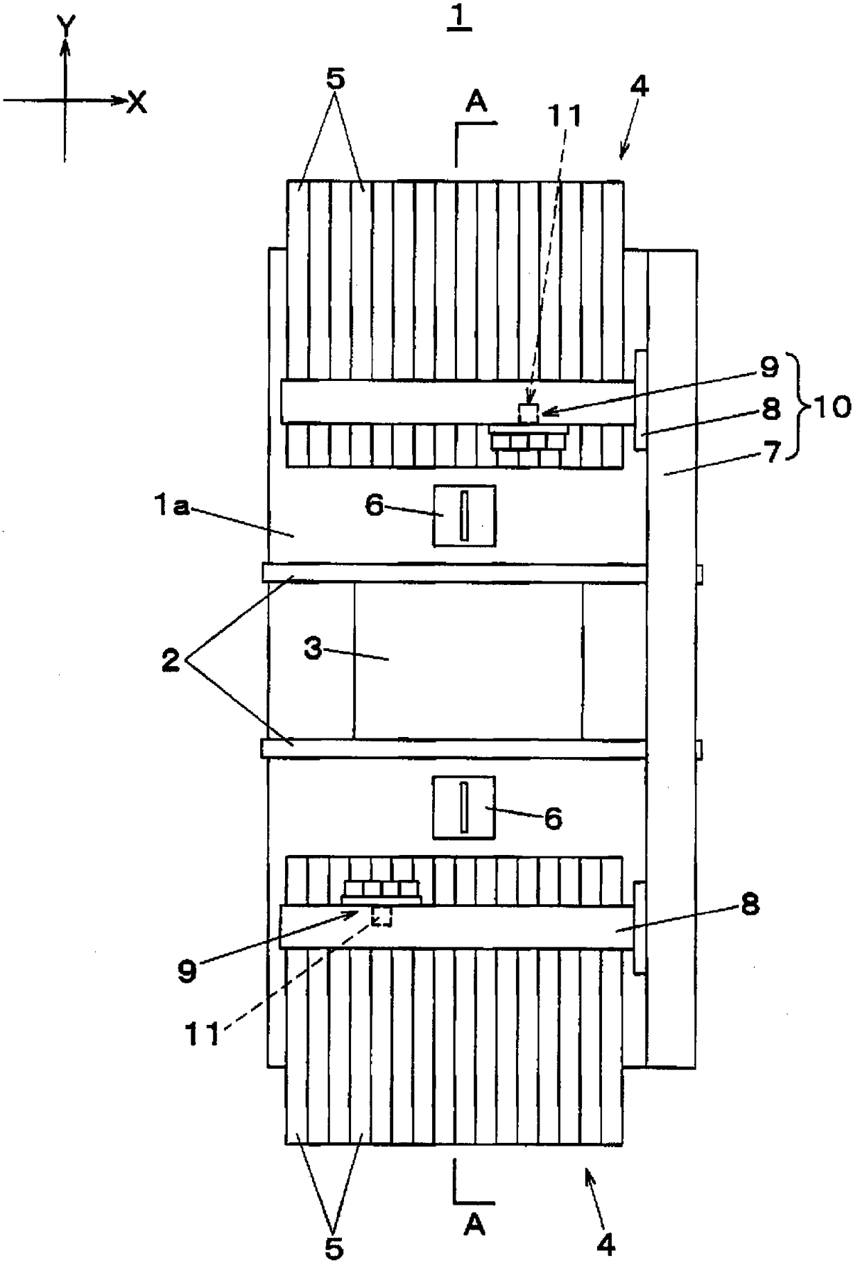
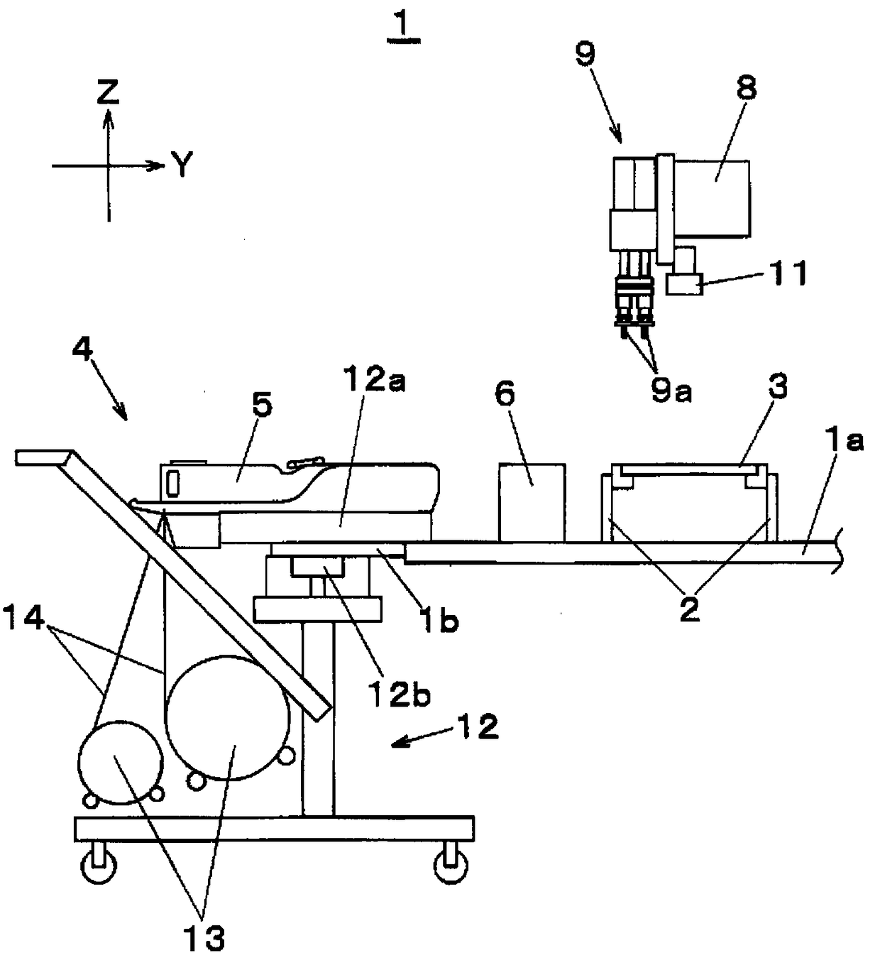
[0032] Hereinafter, embodiments of the present invention will be described with reference to the drawings. First, refer to figure 1 , figure 2 The configuration of the electronic component mounting apparatus 1 for mounting electronic components on a substrate will be described. The electronic component mounting device 1 is used in a component mounting line for producing a mounting substrate, and has a function of mounting electronic components such as semiconductor chips on the substrate, figure 2 locally expressed figure 1 A-A profile in .

[0033] figure 1 Among them, the substrate transfer mechanism 2 is arranged along the X direction (substrate transfer direction) at the center of the base 1a. The substrate transport mechanism 2 transports the substrate 3 carried in from the upstream side, and positions and holds the substrate 3 on a mounting table set for performing component mounting work. Component supply units 4 are arranged on both sides of the board transfer ...


PUM


Abstract

An object of the present invention is to provide an electronic component mounting apparatus and an electronic component mounting method which can achieve both power saving of a tape feeder and accuracy of a stop position of a carrier tape. In the tape feeding process based on the tape feeder, the following operation mode is configured: as an operation mode for specifying an operation mode of a motor driving a tape feeding mechanism, the operation mode is stored with a normal mode and a power saving mode, the normal mode being a mode for executing a normal tape feeding operation and position holding based on an operation command from the electronic component mounting apparatus, the power saving mode being a mode to stop power supply to the motor when the command signal for driving the motor exceeds a predefined set time and is interrupted, and during execution of the power saving mode, the power saving mode is returned to the normal mode if a positional deviation of a rotational position of a sprocket wheel from a prescribed position exceeds a tolerance deviation that is defined in advance.

Description

technical field [0001] The present invention relates to an electronic component mounting device and an electronic component mounting method that take out electronic components from a tape feeder and transfer and mount the electronic components on a substrate. Background technique [0002] As the component supply device in the electronic component mounting device, a tape feeder is often used. The tape feeder supplies electronic components to the component suction position of the mounting head of the component mounting mechanism by intermittently feeding the carrier tape holding the electronic components. element. As the tape conveying mechanism in the tape feeder, a structure in which sprockets engaged with conveying holes provided at equal intervals on the carrier tape are driven to intermittently rotate by a rotary drive mechanism using a motor as a driving source. [0003] In this structure, in order to respond to the demand for reduction in power consumption, a technical...

Claims


Application Information

Patent Timeline
Patent Type & Authority Patents(China)
IPC IPC(8): H05K13/04H05K13/02
Inventor 山村达雄河口悟史清水遵惠
Owner PANASONIC INTELLECTUAL PROPERTY MANAGEMENT CO LTD
Why Eureka
Try Eureka