
Roof bolter

A technology of bolting machine and bolting, which is applied in the directions of installing bolts, drilling equipment, drilling equipment and methods, etc.

Inactive Publication Date: 2014-11-12
兰博有限公司
View PDF6 Cites 1 Cited by
  • Summary
  • Abstract
  • Description
  • Claims
  • Application Information

AI Technical Summary

Problems solved by technology

[0003] A disadvantage of known bolters is that these are usually adapted to fit a specific drill bit and / or bolt

Method used


Image

  • Roof bolter
  • Roof bolter
  • Roof bolter

Examples


Embodiment Construction

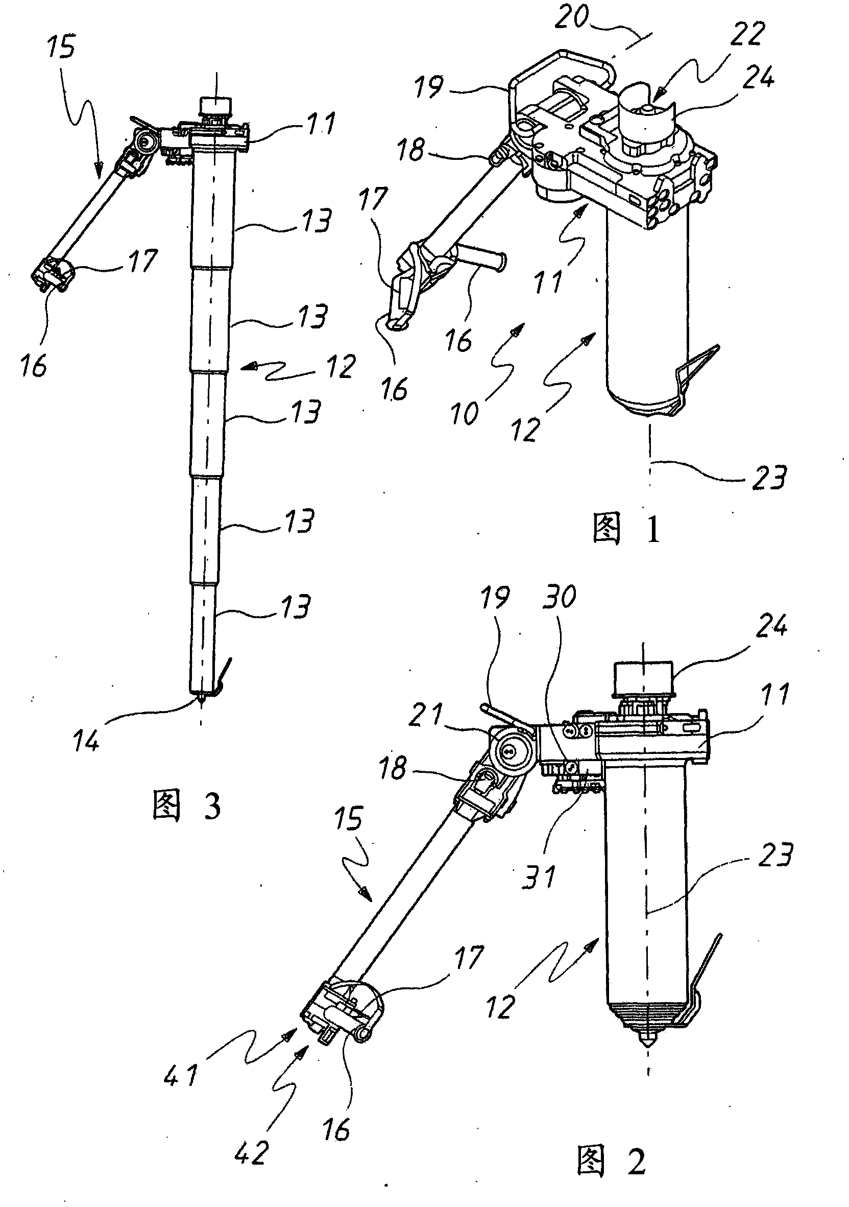
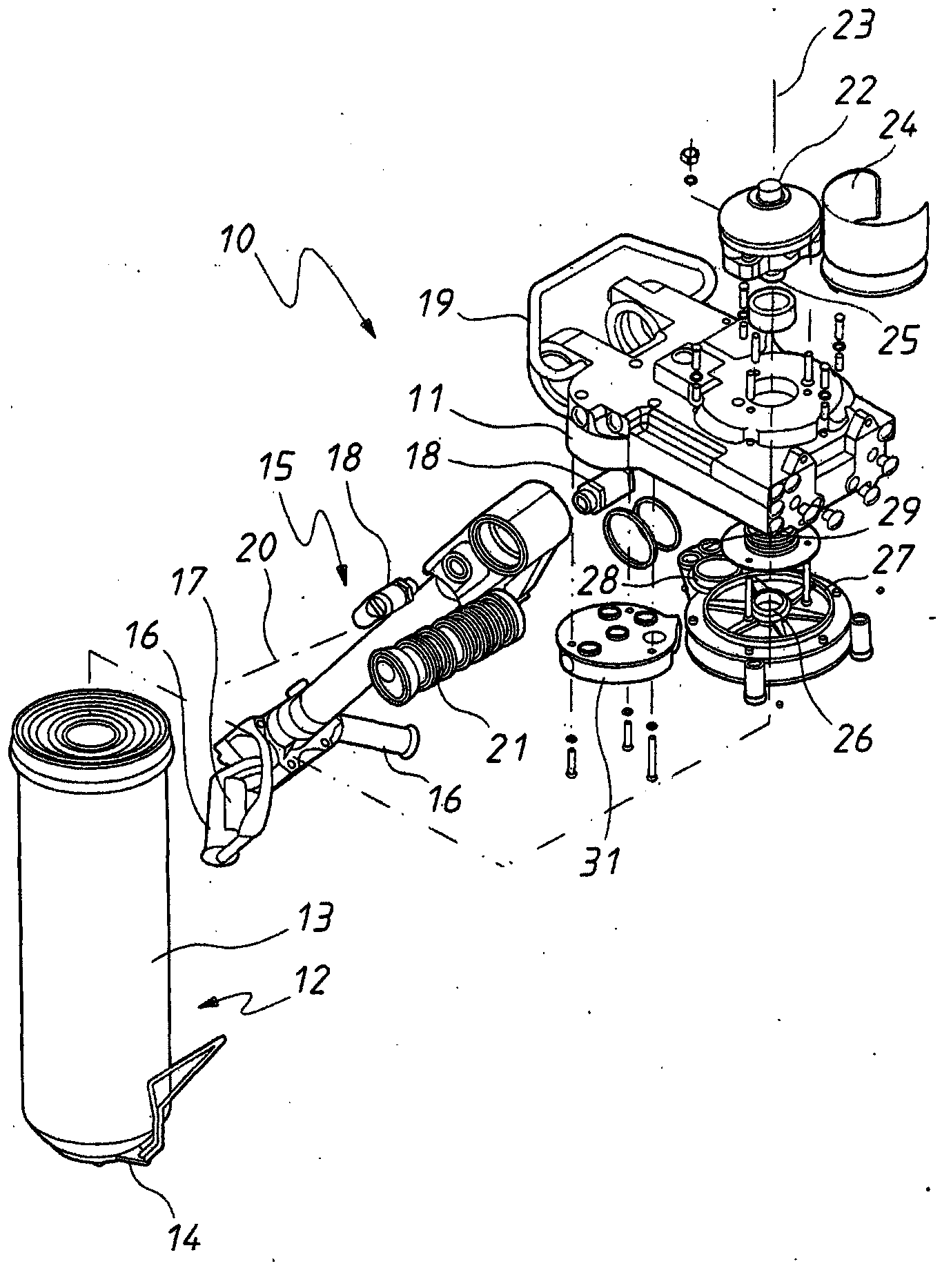
[0043] Figure 1 to 6 The bolter 10 is shown schematically. The bolter 10 is used to receive a drill bit to drill a hole in the rock structure surrounding the drill bit, and then the drill bit is removed and the roof bolter 10 is engaged with and inserted into the hole. In some cases, the storage box is inserted into the hole, and then the top plate anchor is inserted thereafter and rotated to rupture the storage box, so that the resin surrounds the top plate anchor. After the resin hardens, the bolt is fixed to the nearby rock structure.

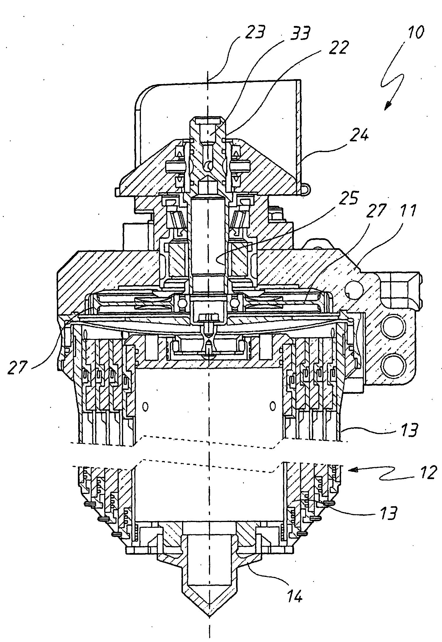
[0044] The roof bolter 10 includes a base 11 supported by a telescopic stand 12. The telescopic tripod 12 has a plurality of sections 13 that can be telescopically received with each other and can be expanded as image 3 The configuration shown. The lowest section 13 has a ground engaging portion 14 that helps to firmly engage the surface of the mine. The uppermost section 13 is attached to the base 11 so that the base 11 is raised or lower...


PUM


Abstract

A bolter (10) intended to receive a drill bit for the purposes of drilling a hole in a surrounding rock structure. The bolter (10) includes a telescopic leg (12) extending from a base (11). The base (11) is provided with a face (30) that is to receive a duct member (31). The duct member (31) provides for the delivery of a drive fluid (such as air) to the motor (29).

Description

Technical field [0001] The present invention relates to bolting machines used in the mining industry, and more specifically, but not limited to roof bolts. Background technique [0002] The bolter is a pneumatic or hydraulic drive device in mining equipment. The bolter is used to install the bolt on the roof of the mine, however, in some cases, the bolter is also equipped with a drill bit to form a hole into which the bolt is inserted. [0003] The disadvantage of the known roof bolters is that these roof bolters are usually adapted to fit specific drill bits and / or bolts. Therefore, it is necessary to manufacture various bolting machines to match various drill bits and various bolts. [0004] Purpose of invention [0005] The purpose of the present invention is to overcome or substantially improve the above-mentioned disadvantages. Summary of the invention [0006] Disclosed herein is a bolter that receives pressurized transmission fluid and pressurized flushing fluid. The bolter i...

Claims


Application Information

Patent Timeline
IPC IPC(8): E21D20/00E21B7/00E21D20/02
CPCE21D20/003E21B7/00
Inventor 彼得·马什塔利日
Owner 兰博有限公司
Learn More