Exposure method and exposure machine

An exposure method and exposure machine technology, which are applied in the direction of photomechanical equipment, microlithography exposure equipment, and photolithography exposure equipment, etc., can solve the problems of low exposure accuracy, limited exposure accuracy, and large graphic size, and achieve high precision Structure, the effect of high exposure precision

Active Publication Date: 2014-11-26
TCL CHINA STAR OPTOELECTRONICS TECH CO LTD
View PDF6 Cites 9 Cited by
  • Summary
  • Abstract
  • Description
  • Claims
  • Application Information

AI Technical Summary

Problems solved by technology

[0004] However, the exposure accuracy of the existing exposure machines is generally low, that is, the precision size that the exposure machines can achieve is not small enough, so that the size of the pattern formed by the photoresist is relatively large.
In addition, there will inevitably be foreign objects on the substrate to be exposed. These foreign objects are higher than the surface of the substrate and the photoresist, so that the distance between the mask and the photoresist cannot be close enough, which is one of the main reasons for limiting the exposure accuracy.
Therefore, there is a problem of low exposure precision in the prior art, and it is difficult to meet the needs of the high-precision structure of the current liquid crystal display.

Method used


Image

  • Exposure method and exposure machine
  • Exposure method and exposure machine
  • Exposure method and exposure machine

Examples


Embodiment 1

[0034] An exposure method provided by an embodiment of the present invention. In this embodiment, the exposure method is used to manufacture the color filter layer on the color filter substrate.

[0035] The exposure methods include:

[0036] S1: placing the mask plate at a first position above the substrate to be exposed.

[0037] Wherein, the substrate is coated with a photoresist (ie, a color filter layer), and in this embodiment, a negative photoresist that is relatively common in the manufacture of a color filter layer is used.

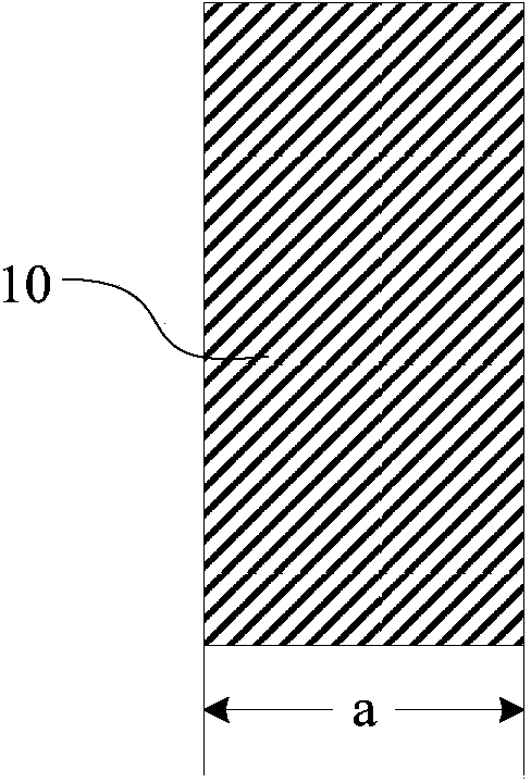
[0038] S2: if figure 1 As shown, a first region 10 of photoresist on the substrate is exposed.

[0039] In this embodiment, the precision dimension of the exposure machine is 8 μm, that is, the minimum dimension a in the first region to be exposed is 8 μm.

[0040] In addition, the conventional exposure dose for negative photoresist is generally 50mJ, but the exposure dose in this step should be less than the conventional exposure dose, and t...

Embodiment 2

[0061] The exposure method provided by this embodiment is basically the same as that of Embodiment 1, the difference is that in step S3, the moving direction of the mask plate is oblique translation.

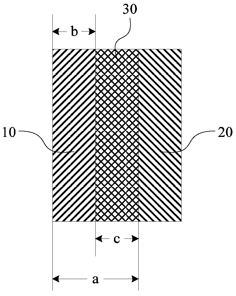
[0062] Such as Figure 4 As shown, after the mask plate is translated obliquely, there is not only a lateral displacement difference b but also a certain longitudinal displacement difference d between the first region 10 and the second region 20 . After the second exposure and development, the pattern formed by the photoresist can not only achieve higher exposure accuracy in the horizontal dimension, but also achieve higher exposure accuracy in the vertical dimension, so that it can be in both the horizontal and vertical directions. It can meet the demand of high-precision structure of liquid crystal display.


PUM


Abstract

The invention discloses an exposure method and an exposure machine, belonging to the technical field of display and capable of achieving a higher exposure precision. The exposure method comprises the following steps: placing a mask plate on a first position above a substrate to be exposed; exposing a first region of photoresist on the substrate; moving the mask plate to a second position above the substrate; exposing a second region of the photoresist on the substrate, so that the overlapping part of the first region and the second region of the photoresist are exposed twice. The exposure method and the exposure machine disclosed by the invention are applicable to a manufacturing process of a liquid crystal display.

Description

technical field [0001] The invention relates to the field of display technology, in particular to an exposure method and an exposure machine. Background technique [0002] With the development of display technologies, liquid crystal displays have become the most common display devices. [0003] During the manufacturing process of liquid crystal displays, the patterning process is utilized many times. Specifically, a mask plate is placed on the substrate coated with photoresist, and then the substrate is exposed using an exposure machine. Depending on the pattern of the mask, the photoresist will have exposed and unexposed portions. Then use the developer to develop the photoresist to remove the exposed part of the photoresist, keep the unexposed part of the photoresist (positive photoresist), or remove the unexposed part of the photoresist, The exposed portion of the photoresist (negative-tone photoresist) is retained so that the photoresist forms the desired pattern. ...

Claims


Application Information

Patent Timeline
Patent Type & Authority Applications(China)
IPC IPC(8): G03F7/20
CPCG03F7/0007G03F7/038G03F7/039G03F7/203G03F7/2045
Inventor 宋江江
Owner TCL CHINA STAR OPTOELECTRONICS TECH CO LTD
Why Eureka
Try Eureka