Air tool motor with built-in striking mechanism

A technology of pneumatic tools and motors, applied in the field of local structure of pneumatic tools, can solve the problems of greatly increased cost, increased heavy feeling, laborious use, etc.

Inactive Publication Date: 2016-03-02
陈秀如 +1
View PDF7 Cites 0 Cited by
  • Summary
  • Abstract
  • Description
  • Claims
  • Application Information

AI Technical Summary

Problems solved by technology

[0004] The conventional setting structure of the striking mechanism is usually to add a front end reversing cover with a considerable axial length at the front end of the air motor of the air tool, so as to be assembled through the front end reversing cover The hammering seat, block hammer, rotary support shaft and other components of the striking mechanism are accommodated; however, because the striking mechanism is protruding from the front end of the air motor, the body of the pneumatic tool is relatively greatly increased. The axial length increases the length of the protrusion formed between the end of the output shaft of the pneumatic tool and the handle. From the perspective of the user, it will inevitably cause a doubled sense of heaviness and more laborious and inconvenient use. ; and from the manufacturer's point of view, the known striking mechanism is protruded at the front end of the air motor, and because of the large increase in axial length and volume, the cost of materials, manufacturing, assembly, packaging, etc. is relatively high. increase, so it is not in line with better industrial economic benefits

Method used


Image

  • Air tool motor with built-in striking mechanism
  • Air tool motor with built-in striking mechanism
  • Air tool motor with built-in striking mechanism

Examples


Embodiment Construction

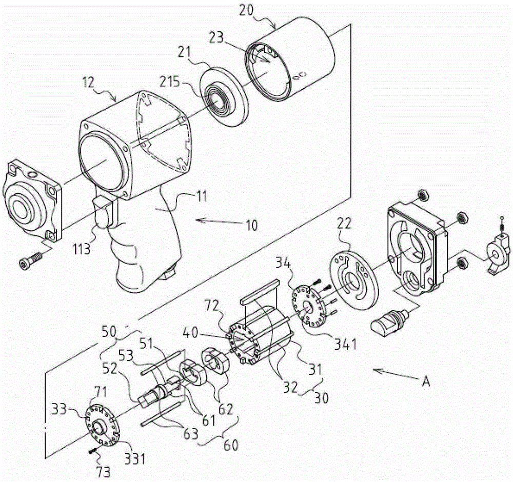
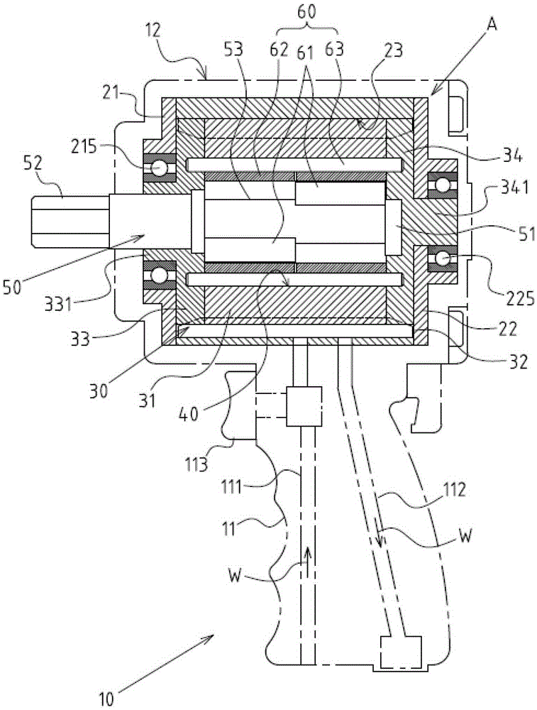
[0023] See figure 1 , 2 , 3, 4, the pneumatic tool motor A with a built-in striking mechanism of the present invention is arranged inside the body 12 formed by one end of the grip 11 (the top end in this embodiment) of a pneumatic tool 10. The grip 11 is detailed as image 3 As shown, it mainly includes an intake passage 111, an exhaust passage 112, and a switch 113 to control the opening and closing state of the intake passage 111; the pneumatic tool motor A includes the following components:

[0024] A cylinder block 20 is in the form of a hollow shell. The cylinder block 20 includes a front end wall 21, a rear end wall 22, and a cylinder chamber 23 inside which is cylindrical. The front end wall 21 is provided with a front end bearing 215, The rear end wall 22 is provided with a rear end bearing 225;

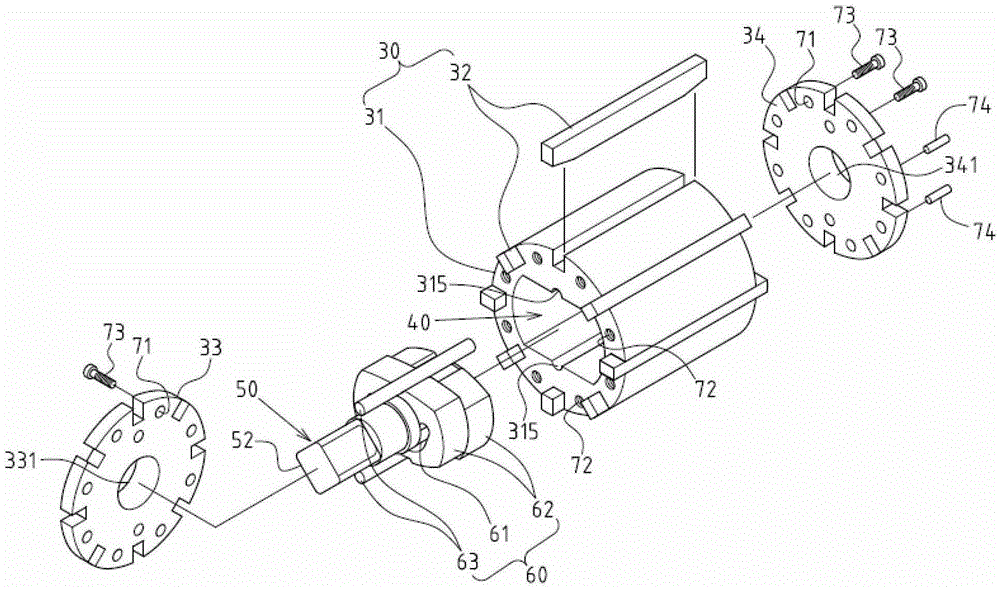
[0025] A rotor group 30 is housed in the cylinder chamber 23 of the cylinder block 20 in a rotatable state. The rotor group 30 includes a rotating drum 31 and at least two telescop...


PUM


Abstract

The invention discloses a pneumatic tool motor with a built-in beating mechanism. The pneumatic tool motor comprises an air cylinder body, a rotor group and an output shaft rod, wherein the rotor group comprises a drum and a telescopic blade, and the output shaft rod can be driven by the drum; an inner containing chamber is formed in the inner part of the drum of the rotor group; the output shaft rod is provided with a beating action zone which is positioned in the inner containing chamber; the inner containing chamber is internally provided with the built-in beating mechanism, and the built-in beating mechanism comprises a beating convex block which is arranged in the beating action zone in a bulged way, a movable beating hammer which is arranged at the periphery of the beating convex block in a sleeving way and a supporting post which is axially located on the drum. According to the pneumatic tool motor with the built-in beating mechanism, disclosed by the invention, the axial length and the volume of the pneumatic tool motor can be substantially reduced, and the advantage and advancement that the use is more labor-saving and more convenient can be achieved; the built-in beating mechanism of the pneumatic tool motor has the advantages that the rotor group can be directly driven, a twisting force can be increased immediately, and the disassembling and the locking of components are quick and convenient, and thus the pneumatic tool motor has the advantages that the multi-aspect cost can be substantially reduced, and the better industrial economic benefit can be obtained.

Description

Technical field [0001] The invention relates to a partial structure of a pneumatic tool, in particular to an innovative pneumatic tool motor with a built-in striking mechanism. Background technique [0002] According to the key, pneumatic tools are mainly used for the locking or loosening of large nuts and screws. Because the tightening torque and the torque required for loosening of large screws and nuts are very high, Therefore, the torque required by itself is relatively high. When the pneumatic wrench is in operation, the torque force is usually generated through the setting of a set of striking mechanisms. The composition and operating principle of the striking mechanism are usually limited and accommodated in a hammer seat There are two block hammers. The hammers can continuously produce an inertial oscillation with the fixed rotation of a transmission shaft in the forward and reverse directions, thereby generating a hammer-type torque-enhancing force. [0003] However, the...

Claims


Application Information

Patent Timeline
Patent Type & Authority Patents(China)
IPC IPC(8): B25B21/02F01C1/344F01C13/02
CPCB25B21/02F01C1/3442F01C13/02
Inventor 张景顺
Owner 陈秀如
Why Eureka
Try Eureka